Radiant Heat. Should I raise the temp?

Hi all,
I have a 2000sqft first floor with 6 zones and 9 loops in NJ. Concrete slab on grade, slab is insulated. This is the first year that the system is running. It's been working really great, keep the house feeling very cozy.
Until today, the radiant was enough to keep the house at a comfortable temp. It's getting colder outside, and today was the first day that we needed to supplement using the forced air system.
Temperature going in to the slab is 120°. Coming out of the slab is 90°. Flooring is engineered wood besides for 2 rooms (400sqft total) which is carpet.
Should I raise the temp of the water? Or I risk damaging the wood floor and I should just use the forced air to get us over the hump?
Thank you all!
Comments
-
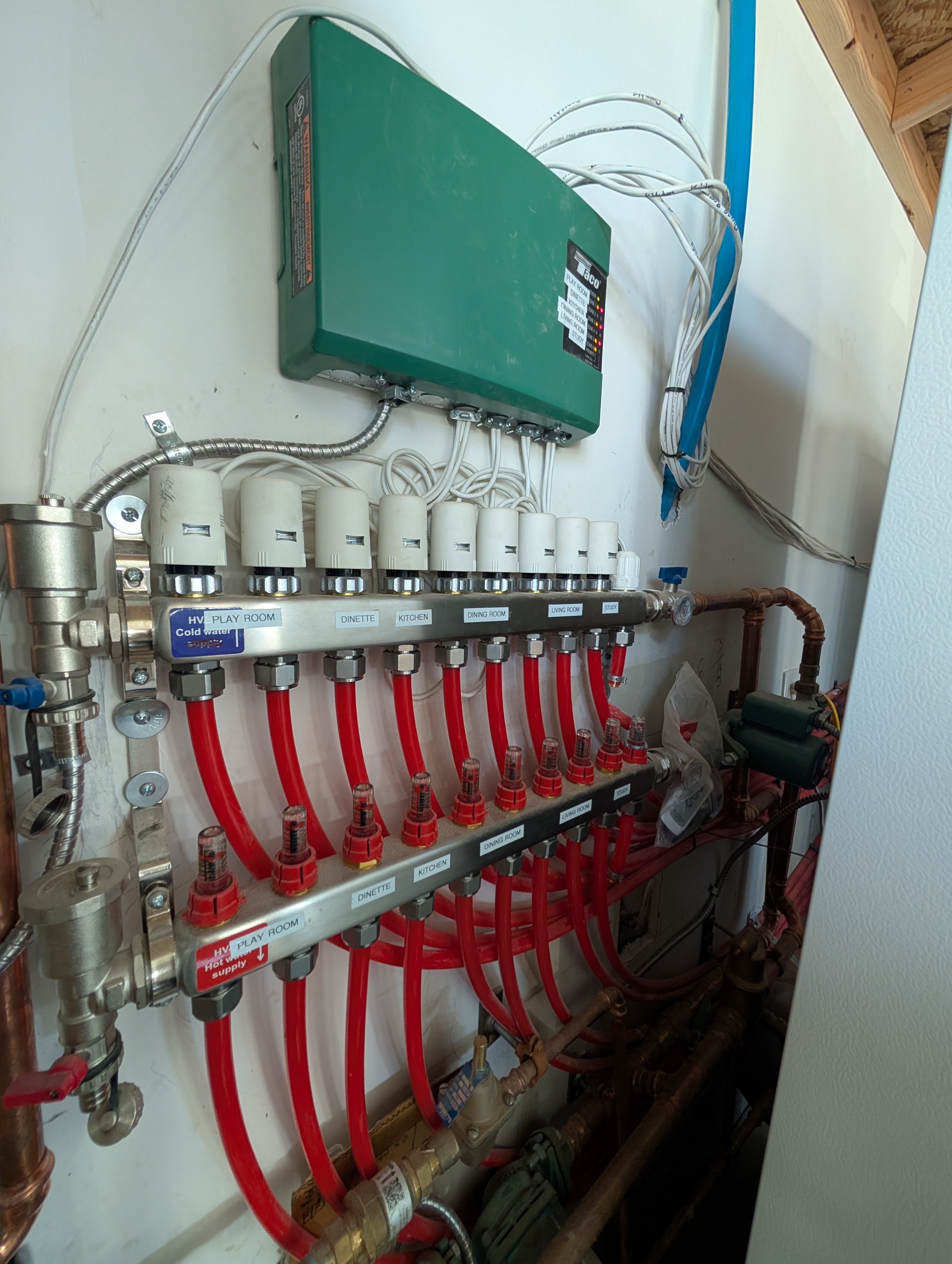
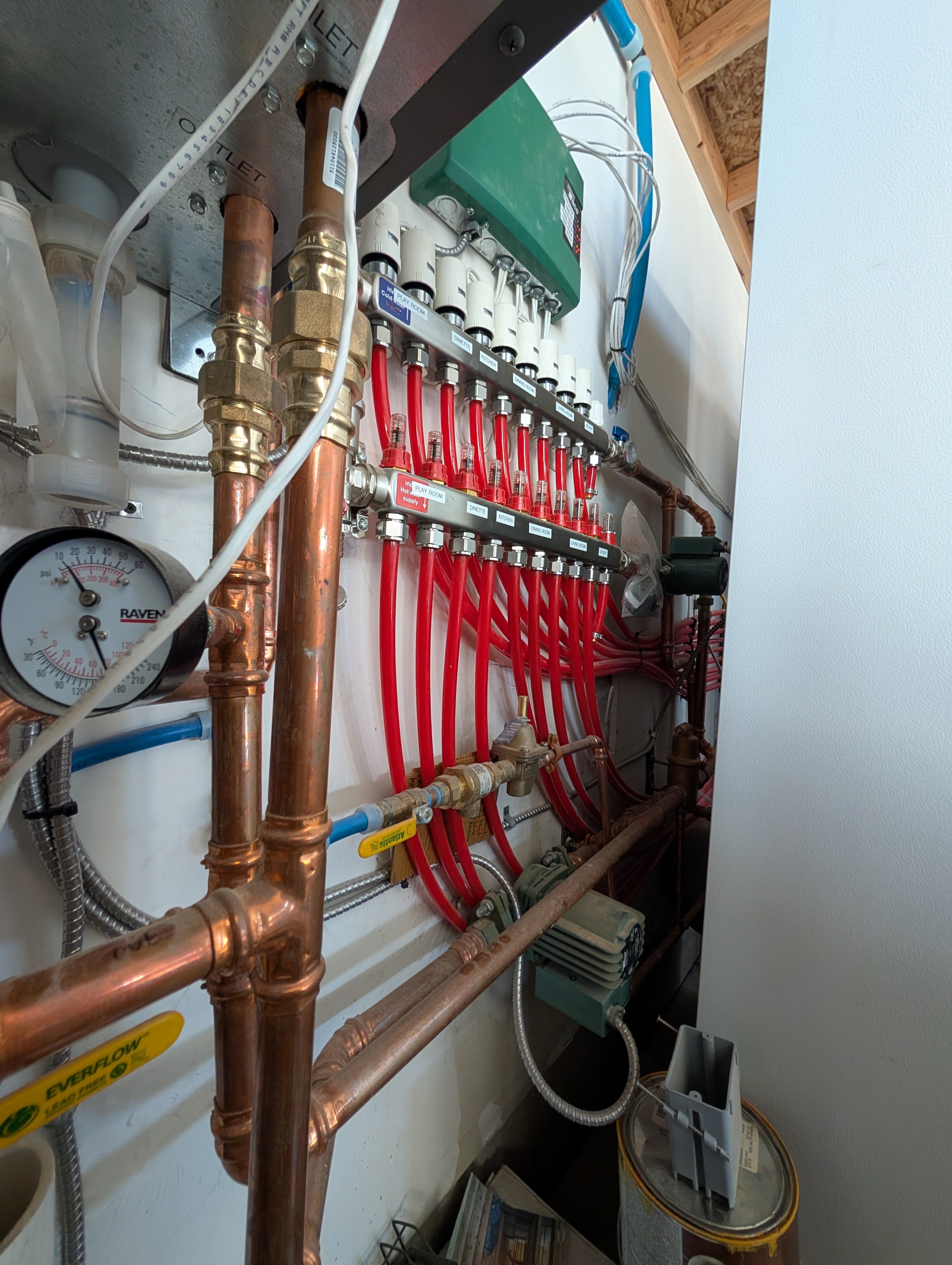
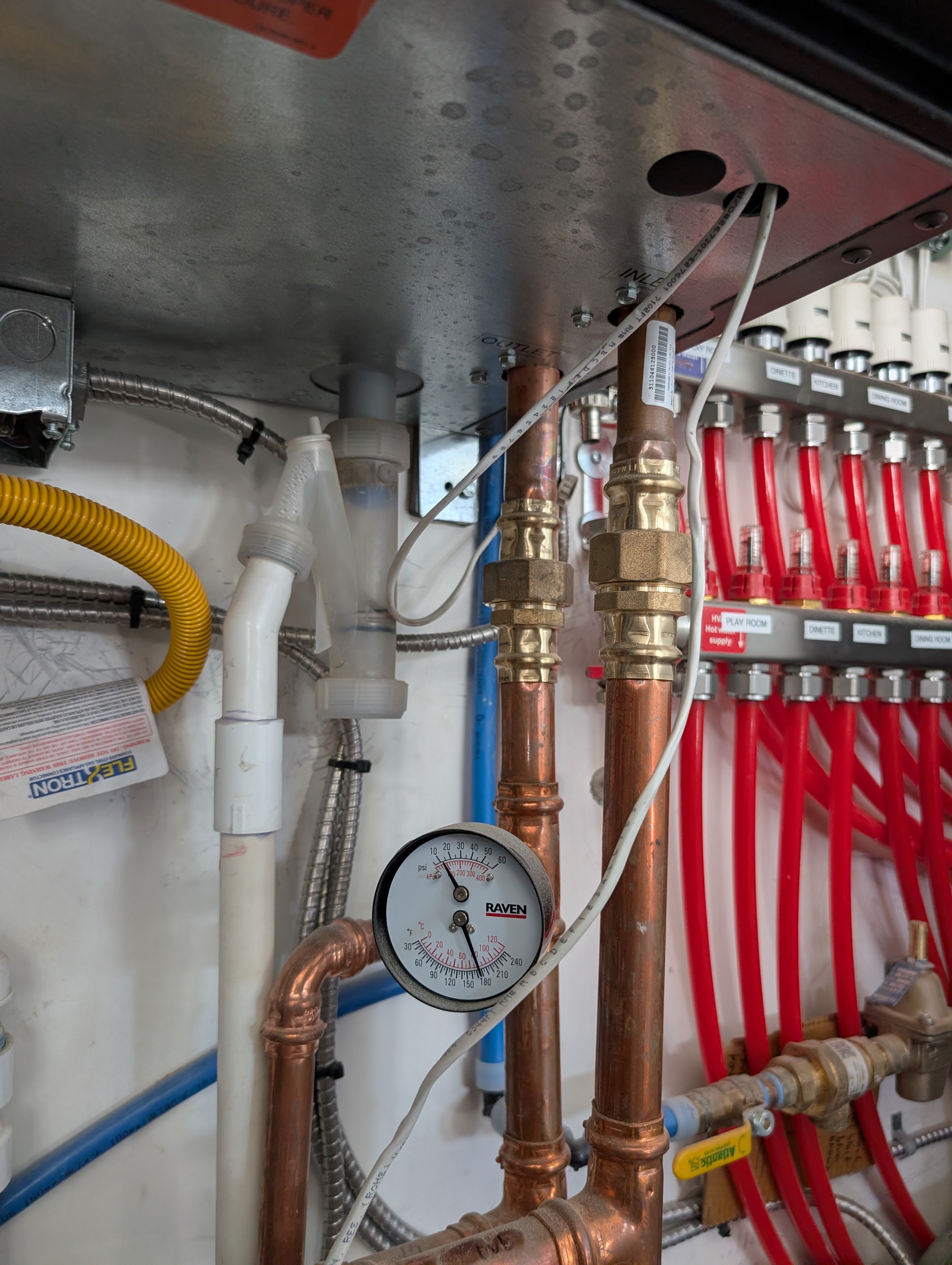
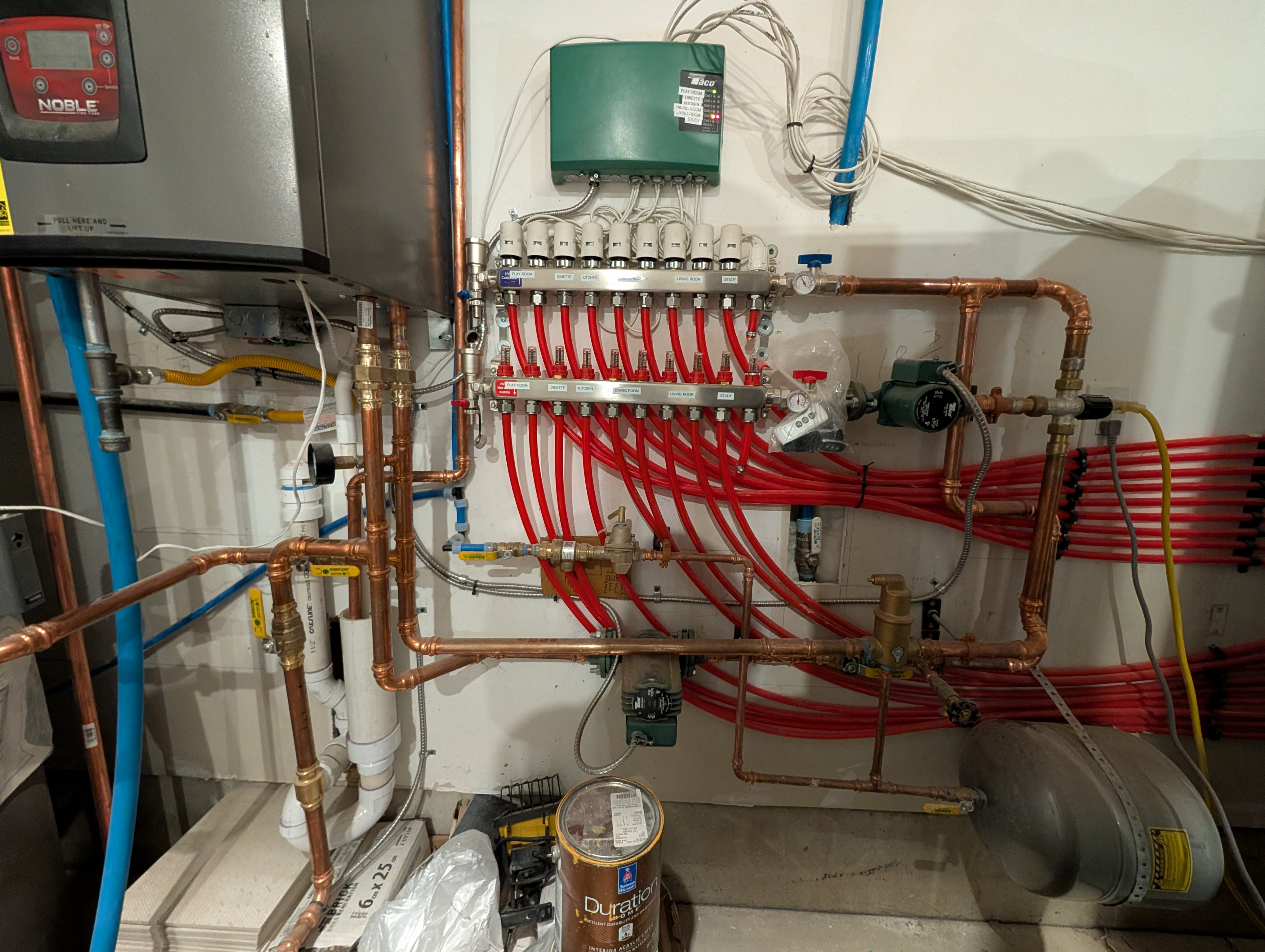
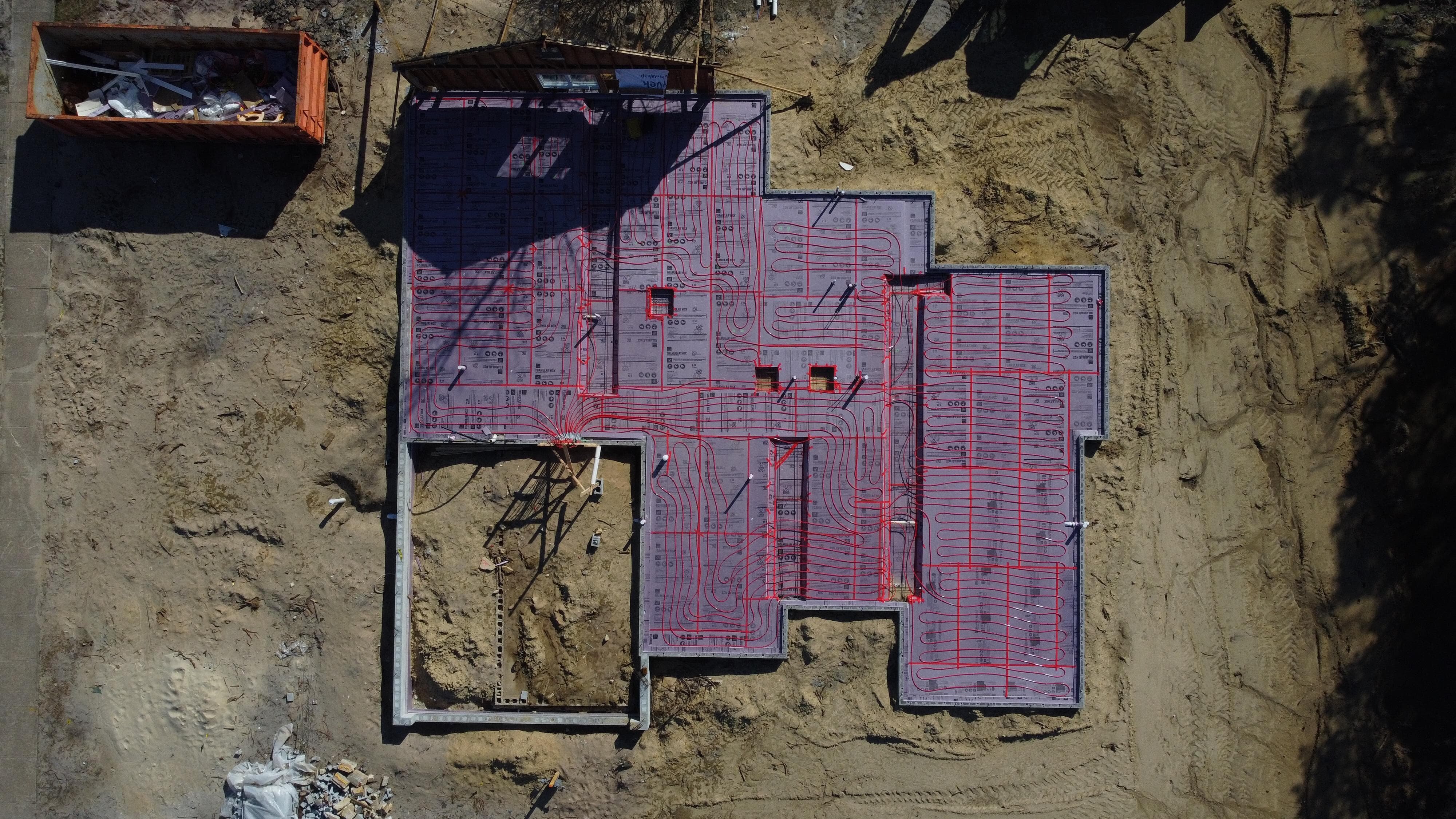
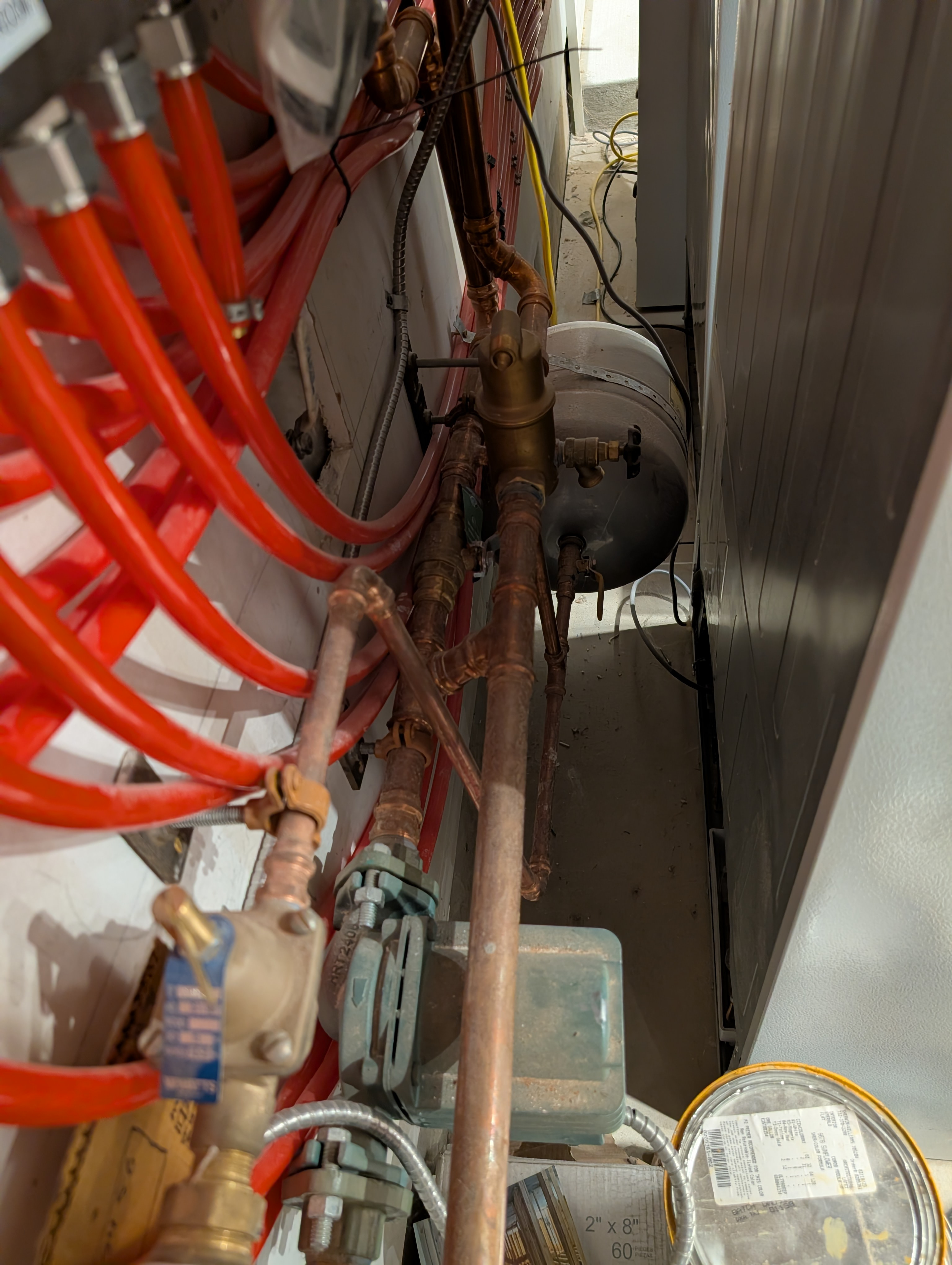
Here are pictures of my setup in case it helps answer the question.
0 -
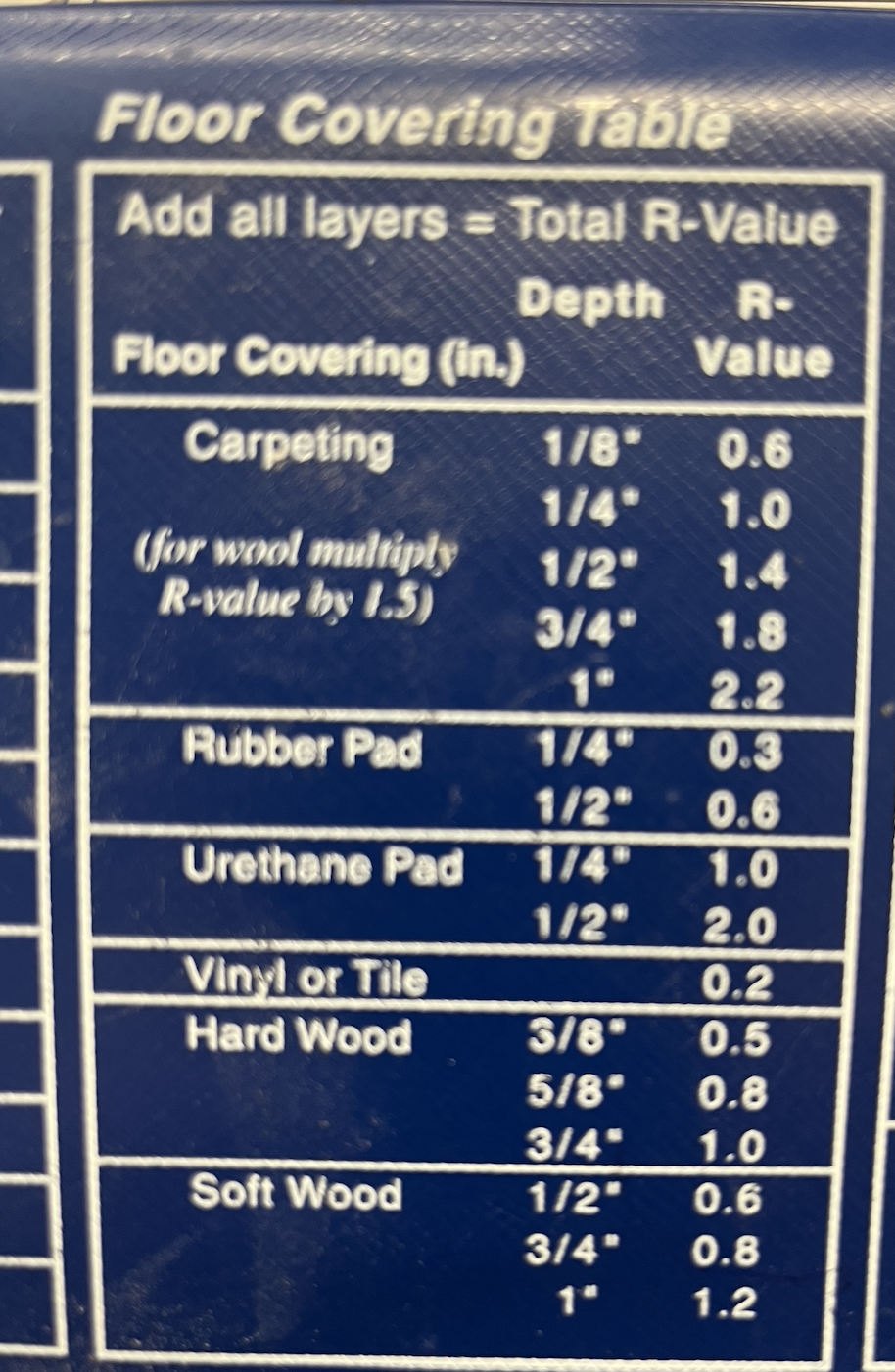
Carpet with pad below? That could be a tough go for radiant heat. Here are some examples of R-value for floor coverings
The slab surface temperature is what you want to know and then see what the wood flooring manufacturers allow. If it is glue down flooring, check the adhesive limitations.
Was a heat load calculation and design done for the system? That would show how the carpet dictates the floor btu output.
That 120- 90 is a wide delta, 10- 15 is typical for residential home radiant. It depends on when you measure that ∆. If you could increase the flow rate the floor surface would even out, be more consistent across the surface and may helps.
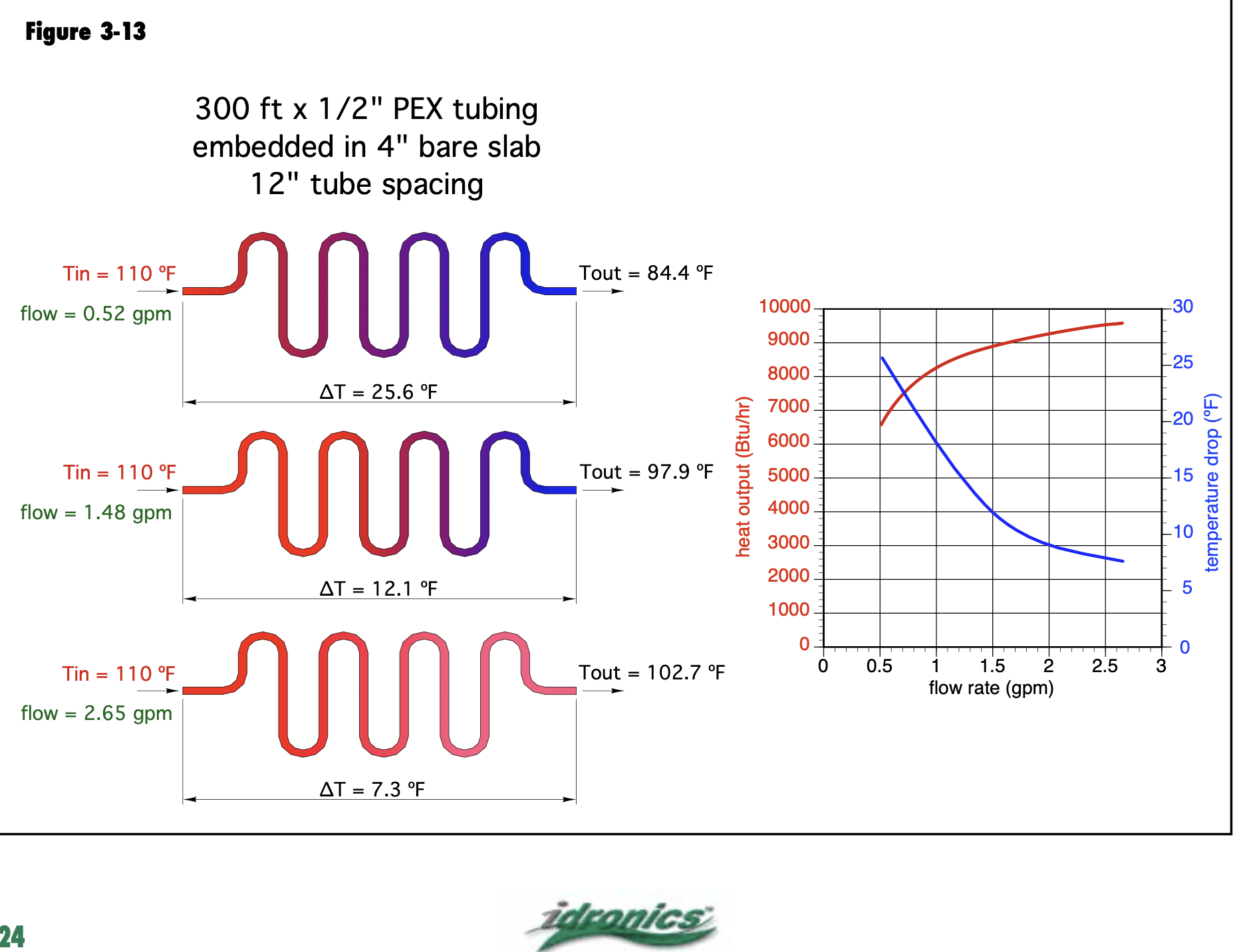
Increasing temperature or increasing flow will get you more btu/ ft output. This graphic shows the result of the loop temperature from beginning to end as flow is increased, same SWT.
There is a point of diminishing return, from .5- 1 gpm you see a good boost, the red output curve starts to flattens at around 1.5, it is may not be worth the pumping power to get higher flow rates for minimum increase. You have flow meters on the manifold 1/2" loops you could push .75- .80 gpm maybe, through the under-heating loops.
How long are the loops? What tube spacing? Plain water in the system? Your manifold pump will be the limit to what you can actually flow. It's nice to use a multiple speed circulator to get some adjustability.
You want to measure the loop delta after it has been running for a period of time. When the supply and return temperature stabilize, that is thermal equilibrium, measure at that point.
The delta is ever-changing in hydronic systems it is not something that you can "set" the load at any given point in time, how much heat the loops dissipates, that determines the operating delta.
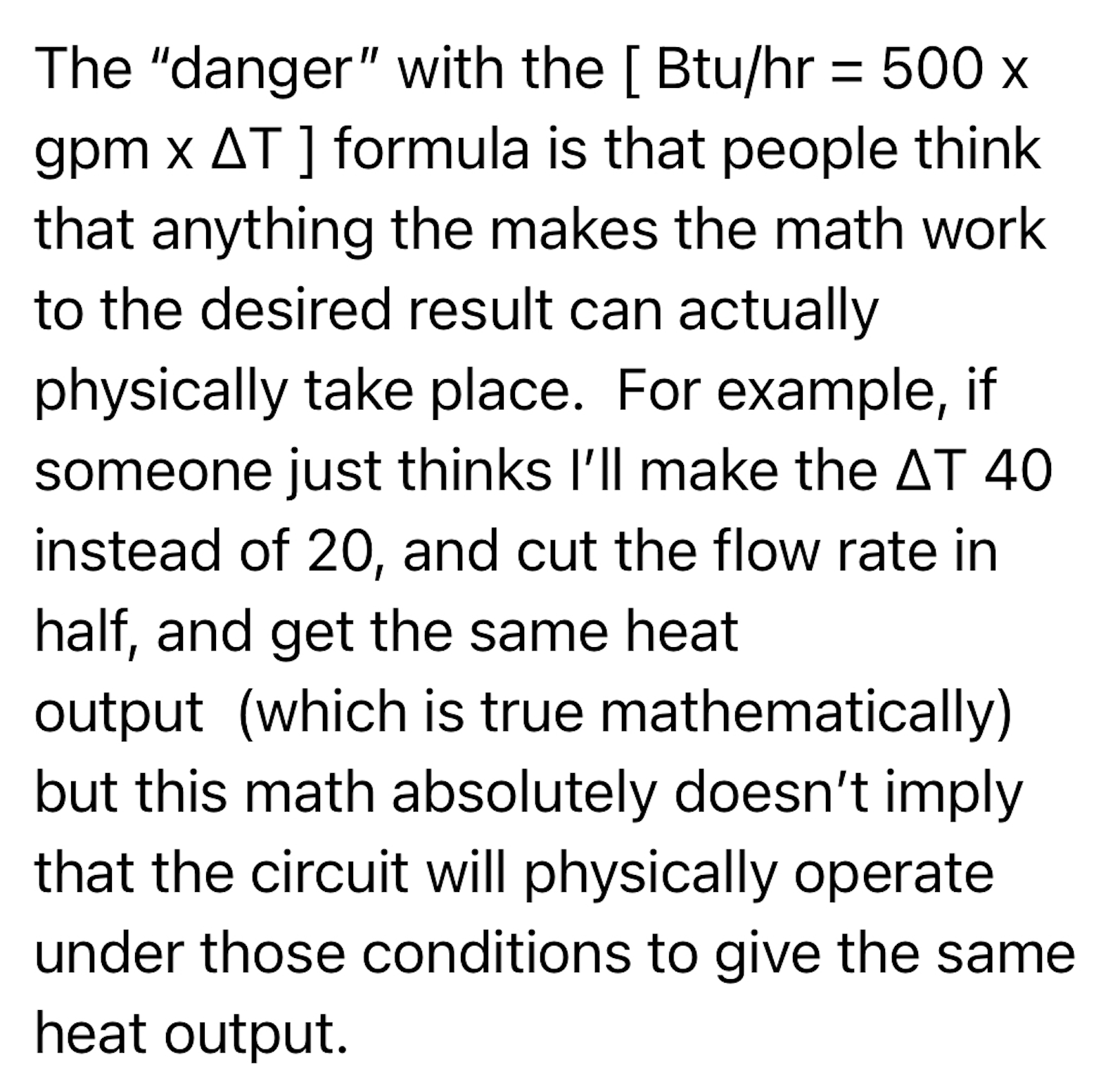
Trust the onsite measurements to determine the output, the universal formulas can deceive as my mentor explains it.
 Bob "hot rod" Rohr
trainer for Caleffi NA
Living the hydronic dream
 3
3 -
Generally the limiting factor is going to be how hot you can stand to walk on, once it gets past about 90F it starts being uncomfortable. If you're standing a lot even lower could be a problem. Building materials shouldn't have any trouble with those temperatures, on a summer day the inside of an unconditioned house will get hotter than that.
There's no shame in letting the air handler take some of the load. Keep the floors at a temperature that's comfortable for you. The entire reason for heating is comfort.
0 -
Thats super helpful. Makes sense that I need to increase flow rate. Any upper limit? Any reason not to push the flow rate as fast as possible so I get the most even heating between the beginning and end of the loop?
0 -
@buildhouse : "Any upper limit? Any reason not to push the flow rate as fast as possible so I get the most even heating between the beginning and end of the loop?"
You run into diminishing returns. The amount of heat released by the floor is determined by the temperature difference between the floor and the air in the room.
Let's say you've got water going out at 120F and returning at 90F, that's an average temperature of 105F. Let's say that you're getting that with 0.25 GPM, so you're delivering (120-90)*0.25*500= 3750 BTU/hr.
Let's say now you turn the flow up so that it's going out at 120F and returning at 110F. Average temperature is now 115F. So instead of 35F above room temperature you're 45F above, so your heat output is 45/35 times as much, or 4821 BTU/hr. To get that with a 10F water temperature drop you need 0.96 GPM.
Let's say you turn it up so now it's coming back at 115F. Average temperature is 117.5. Output is 5089 BTU/hr, flow is 2.04 GPM.
Now turn it up so it's coming back at 119F. Average temperature is 119.5F. Output is 5303 BTU/hr, flow is 10.6 GPM.
As the temperatures get closer, you get smaller and smaller BTU increases and require bigger and bigger increases in the flow to get them.
0 -
@buildhouse : "Any upper limit? Any reason not to push the flow rate as fast as possible so I get the most even heating between the beginning and end of the loop?"
YES
There is a sweet spot that will maximize the output of your floor. Right now at 30°∆T you may not be getting all the BTU that floor can do. If you get the flowrate so fast that you only get a 5°∆T the water will have less time to give off the heat it contains. That slab may even get colder since the heat is not staying in the slab as long. If the water can't give up its heat to the slab, and collect some of that cold slab temperature, then you will be back in the same place. Not enough heat.
I would look to get a 10° to 15° ∆T and see if that gets you to a colder outdoor temperature. The Radiant floor heat I did in my home in Brigantine NJ was optimized to provide heat to about 16° outdoor temperature. Below that the original gas furnace kicks in.
I have an outdoor thermostat in series with a heat relay on the boiler to close a set of contacts on a call for heat. If the outdoor temperature temperature then gets below 18°F the contacts close and allow the furnace to supplement the call for heat. That satisfies the thermostat and also turns off the radiant floor boiler but when the room temperature drops again the boiler and the furnace both operate to heat the home again. Not the best logic for that system but it was easy.
Some of you may be tempted to tell me how to make it better with a two stage thermostat and all that… I don’t live in NewJersey anymore so I can't just pop over and fix it. It Is What It Is.
Edward Young Retired
After you make that expensive repair and you still have the same problem, What will you check next?
0 -
Ok. My GPM right now is about .4
Looks like I should approx double that.
I guess I need a stronger pump.
0 -
I have to disagree with Eds statement here :)
Truth is Higher flow, tighter delta= higher AWT = hotter overall heat emitter = higher BTU output. You cant cheat the laws of thermodynamics
1 Hot goes to cold always
2 The rate of heat exchanges is based on the ∆. Hotter emitters in a room that is of any lower temperature increases the heat output.
Various ways to get there.
Heat exchangers that we maximize transfer from run tight ∆. Solar thermal we look for 3-5°. We want heat in the tank as fast as possible the avoid loss to the ambient.
Plate heat exchangers can design to "close approach" temperature with 3° with high flow rates.
Every single heat output chart you find for any heat emitter shows a selection of flow rates ∆s to see output differences.
Putting a fan behind a finned water coils (forced convection) "speeds up" the air movement, "speeds up" the heat output. It works on both fluids and air.
Google this article.

Floor coverings limit the amount of BTUs you can deliver. Base slabs, tile floors, and hard surface you want to keep around 82° surface. 82-70 X 2 = 24 btu/sq ft as a reasonable heat delivery. Colder ambient increases output 82-65 X 2 =34 btu/ sq ft. That may be fine in a work shop, but 65 ambient is a bit cold for my home :)
Perhaps the first part of a loop is a bit higher surface, above 82° it dissipates as it travels. The AWT tells more of a story.
It is easier and more linear to increase heat output by increasing SWT- AWT, instead of flow increases..
You cannot "fix" a delta T in a system, it goes where nature takes it! Trying to fix or "constrain" a ∆ is basically putting the brakes on the system. Loads are dynamic in a home, building, let your hydronic system also be dynamic, it will find thermal equilibrium if you don't screw it up :)
If you are a just a bit short, a few degrees try upping the SWT 5° first. You have the ability to do that without any component changes.
Bob "hot rod" Rohr
trainer for Caleffi NA
Living the hydronic dream2 -
I agree with @hot_rod here. Increasing the flow always increases the average temperature and increases the heat output. There's never a point where increased flow leads to lower output. The issue is diminishing returns; the higher the flow, the less additional heat you get from increasing the flow.
0 -
your manifold pictures seem to show 2 loops, in 2 different zones, not pulling down the flow indicators, look at study and living room, even the others look like some additional balancing might help,
known to beat dead horses0 -
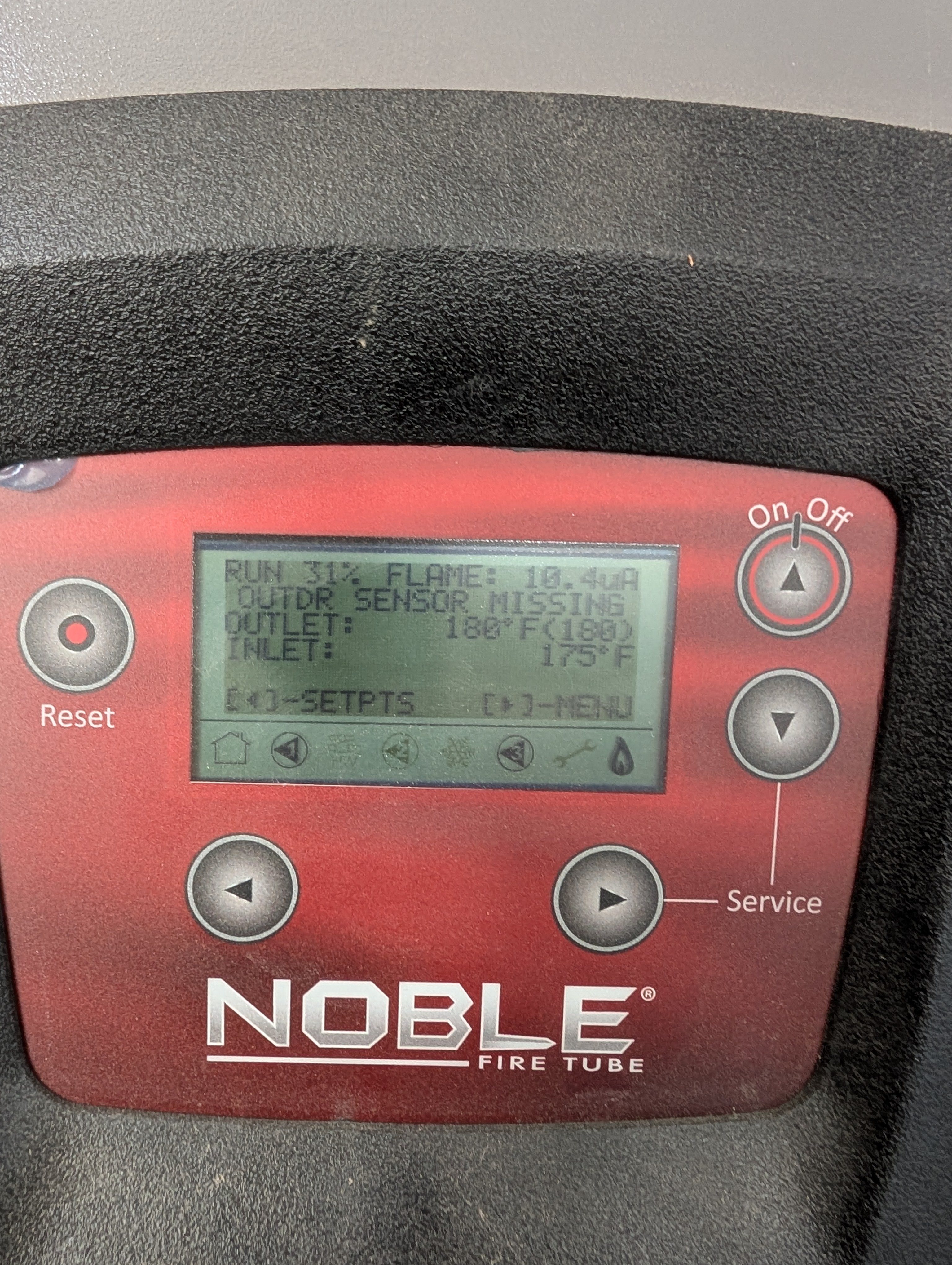
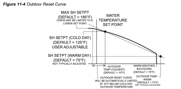
The control readout indicates "outdoor sensor missing". You want to connect that sensor and use the ODR function.
Here is how it works, by modulating the boiler supply temperature as outdoor temperature drops. This helps keep the boiler running long efficient cycles.
It want to match heat loss with boiler output. Comfort, fuel efficiency, boiler cycling all benefit from using this function.
 Bob "hot rod" Rohr
trainer for Caleffi NA
Living the hydronic dream1 -
"The amount of heat released by the floor is determined by the temperature difference between the floor and the air in the room. " YES, YES, YES!
Heat energy moves to what ever is coldest, Up, down, sideways. However, the heat in the floor must be there, which is dependent on SWT and Flow. There must be a temperature differential as you understand or no heat energy can transfer.
The upper limit output of heat energy you can put into your radiant sys is dependent upon floor construction, floor covering, and radiant design (tube layout). So, how hot can you run your SWT before you change the cosmetic look of your floor covering (wood)? It depends. On plank wood flooring, shooting with a laser thermometer, I don't like to go much over 85 deg surface temperature even tho the SWT is 140 degs.
(SWT), it's based upon construction and floor covering and measured floor temperature. What does your floor manufacturer say. You can boost the SWT 5 degs at a time and observe the result by shooting the floor with a laser thermometer (guess work).
0 -
Exactly!
Tube spacing and their depth in the slab will also determine what SWT is required to get the needed floor surface temperature.
Bob "hot rod" Rohr
trainer for Caleffi NA
Living the hydronic dream1 -
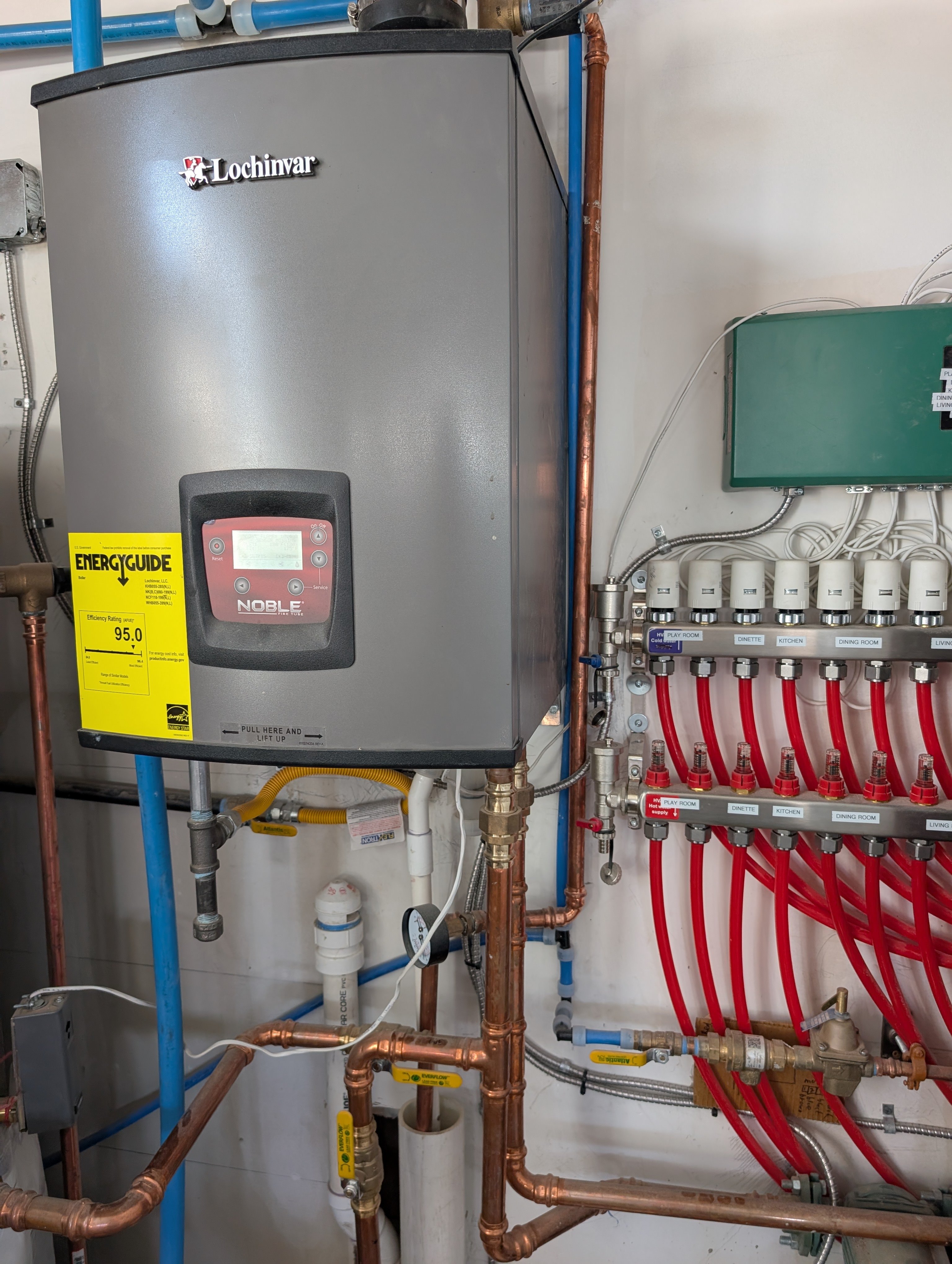
Well for starters, it's piped extremely wrong and set to 180 degrees for absolutely no reason. Get the installer back to do this correctly before you start worrying about floor temps
0 -
Can you explain what's piped wrong here? (This was a diy install with some help from a friend who was also trying to figure it out)
0 -
You have to take pics from further back. Your pics so far look nice and clean, I like that.
"This was a diy install with some help from a friend who was also trying to figure it out…" Sound ok to me. Sorry, I'm a funny guy. Your friend's a keeper.
0 -
When I see this situation, couple thing to look for:
- what does the heatloss and the radiant design dictate the water temp to be?
- Large delta t tells me that there may be not enough flow, what is the gpm and head loss of the system and what circ is being used. Mixing valve? The design from above will answer that as well.
- is the edge of the slab insulated properly? And what type of insulation used? It is very easy to insulate under the slab, but the edge construction get overlooked often and that is where alot of the heat loss of the slab goes. Get a temp reading of the edge of the slab outside
Dave Holdorf
Technical Training Manager - East
Taco, Inc
1 -
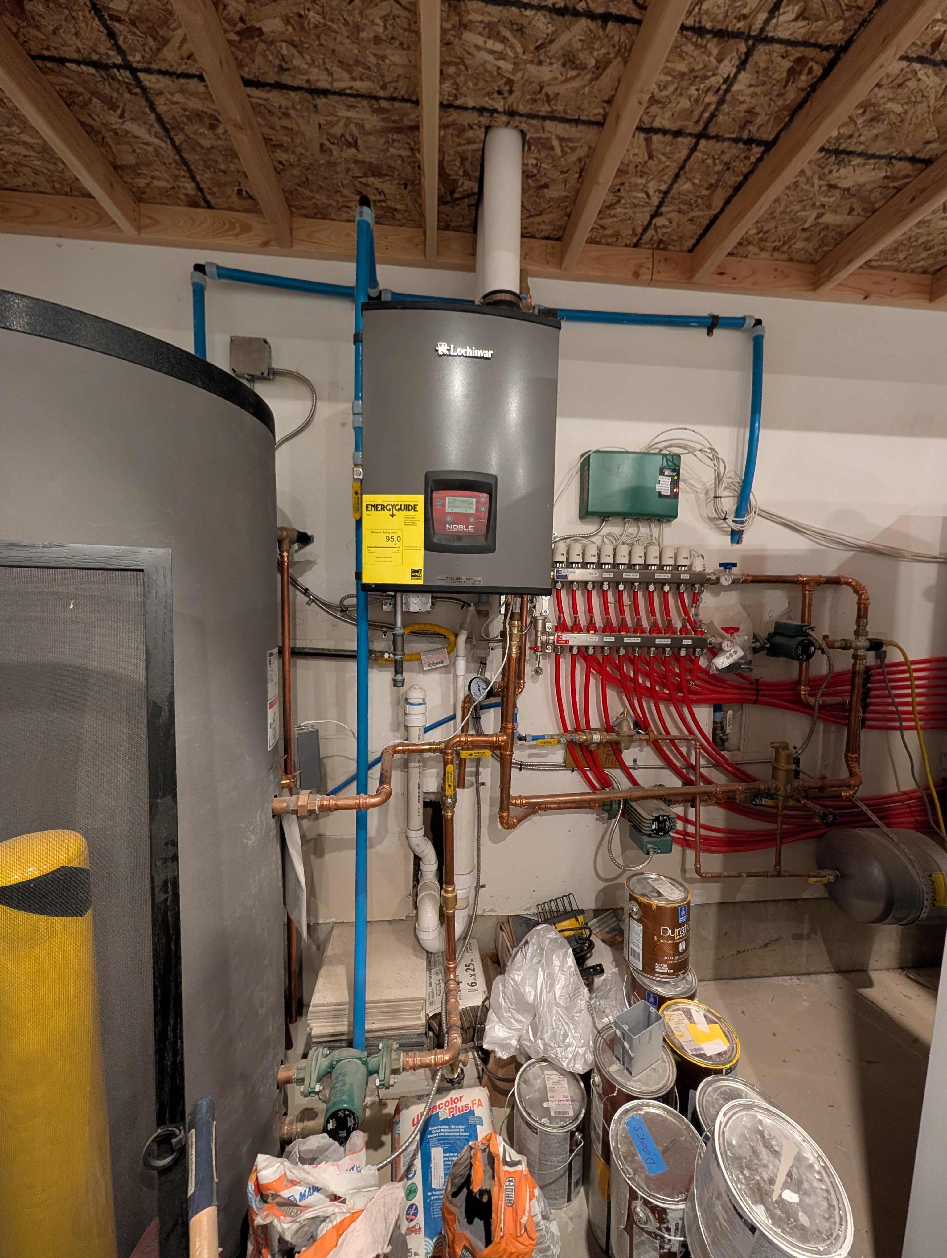
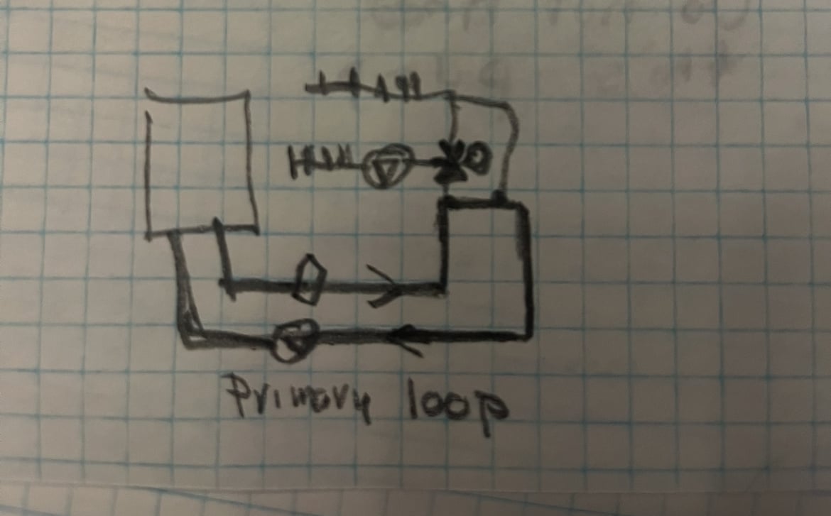
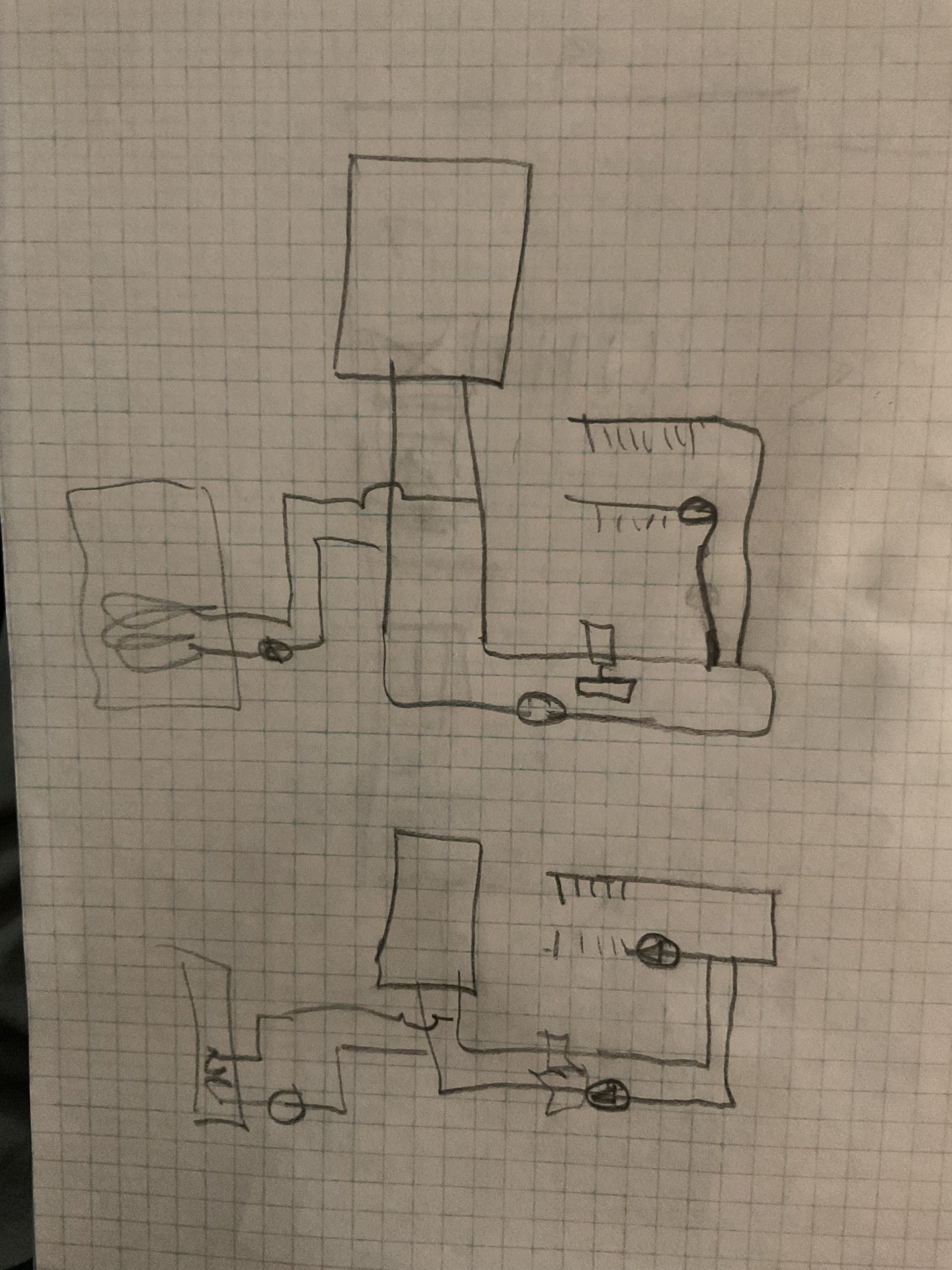
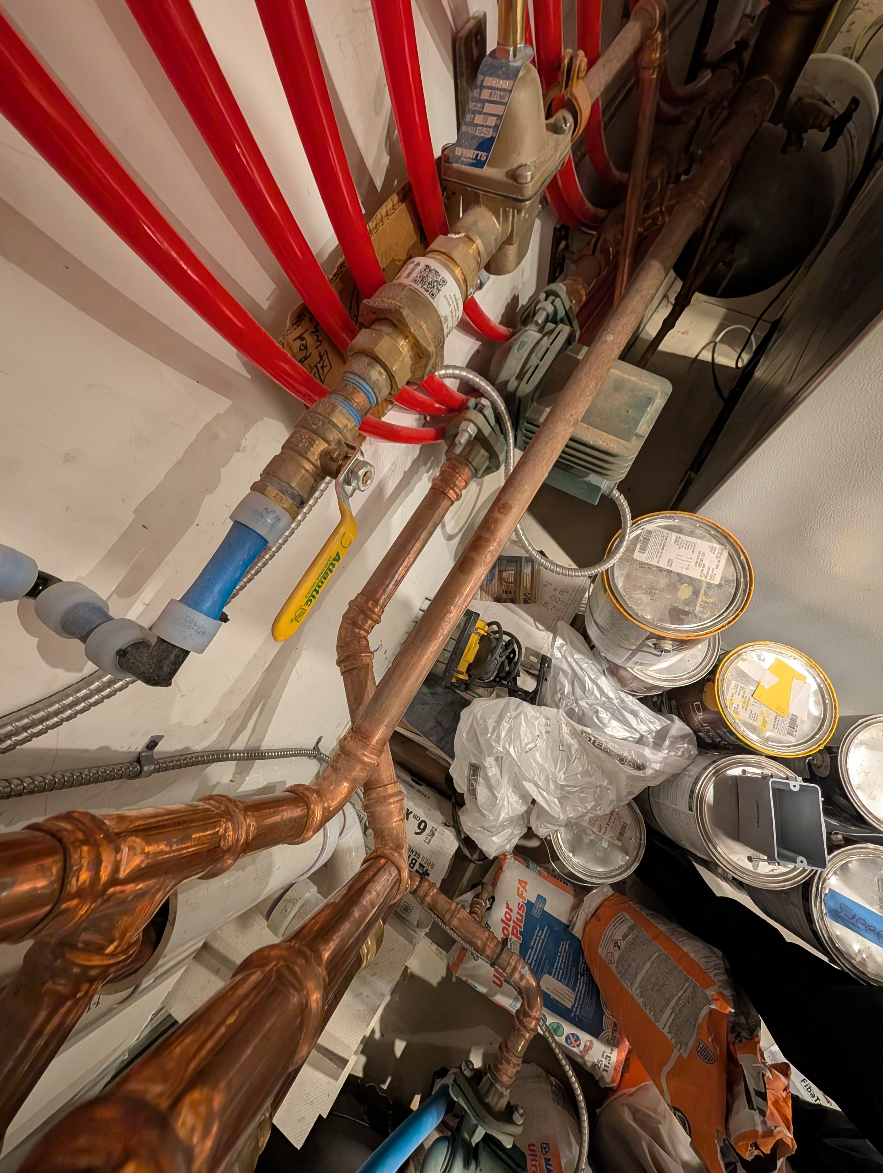
This is the whole system!
0 -
I have to check the program to get the numbers…
Edge of the slab is insulated, we were very careful about that.
0 -
A thermostatic mixing valve to regulate SWT is not the best choice. It has a high resistance to flow (a low Cv). I would prefer a valve with a higher Cv. A Taco I-series with a sensor mixing valve would have been my choice. A circulator (pump) doesn't suck, it circulates.
Doesn't appear to me to be piped primary/secondary. I assume you have the necessary check valves. (volute?)
 1
1 -
Unfortunately, There does seem to be some issues with how it's piped. The two circulators look like they could be fighting eachother. Plus potential for circular flow through the mixing valve/boiler if no check valves (maybe that was intentional?) After getting more advice on this forum and piping diagrams, I would repipe it in the spring if it was mine. Including getting rid of the mixing valve(and extra circulator), put in primary/secondary loops, set the circulator to pump away from exp tank, and set up the ODR.
0 -
That Taco I series is a bloody fortune!! Any other way of doing this?
0 -
close!, connect supply from boiler to return, now you have a loop for the boiler with the lower taco circulating it.
The 3 way connects to the loop with close spaced tees
Any idea how many gpm the loops need?
Assume .5 x 9 loops? How long are the loops?
That is probably a 3 Cv valve maybe larger if it is a Honeywell radiant version?
You should be able to flow 4.5 gpm to the manifold once the piping is correct
 Bob "hot rod" Rohr
trainer for Caleffi NA
Living the hydronic dream1 -
Unfortunately, prices are going up on everything. The value of the dollar is going down. You can look for alternative mixing valves that have a higher CV and are less expensive.
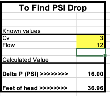
Because I don't know the pex loop lengths although you can look at the foot writing on the tubes which has a number on the supply and a number on the return and subtract them to get the circuit length and to get some idea of the flow rate for each loop when all the 9 circuits when all are open.
A flow rate of .45 GPM on a 100' loop is going to act differently than a 300' loop at the same flow rate. You can actually run out of heat energy before the water exits the circuit. Delta T will give you some idea of the flow that each loop needs. However, heat transfer is fluid and depends on other things and that is what the goal is, getting heat energy into your living space. Like Love, hydronics is complicated.
0 -
4.5 gpm through a 3 Cv valve looks like this
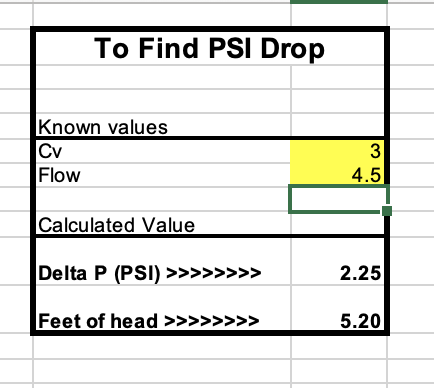
If we knew exactly what valve you have, the numbers could be adjusted.
Some thermostatic mix valves ship with checks and strainers in the H&C port. If it is an ASSE 1070 or dual listed 1017/ 1070 checks are required in the valve. Pull those checks and strainers out of a valve used on hydronic systems, too much potential for plugging.
Checking and cleaning the 3 way may get you where you want to be.
A dirt separator is a must if you have crud in the system, however.
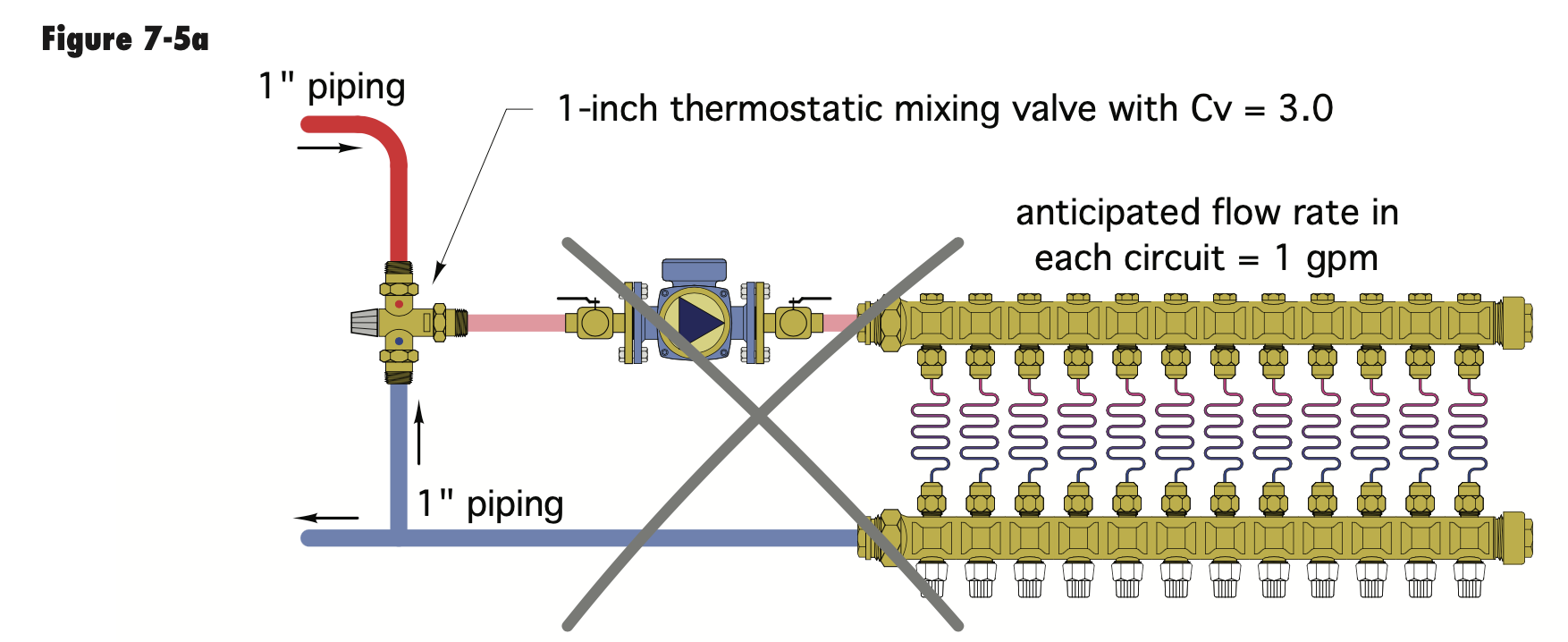
Here is an idea of where you get into trouble, high flow loops and many of them.
 Bob "hot rod" Rohr
trainer for Caleffi NA
Living the hydronic dream0 -
-There is no hydraulic separation
-The boiler pump is pushing directly at the mixing valve
-There is a mixing valve
The installation manual is very clear in their piping diagrams and none of them are anything like this. Remove the mixing valve entirely, repipe to manufacturer spec with hydraulic separation (and probably a buffer tank to prevent short cycling with only 1-2 loops calling for heat at any given time), connect the outdoor sensor, and set the outdoor reset curve to attain the proper water temp right from the boiler (seldom more than 110*). If wired correctly, the boiler will raise the water temp to its desired setpoint during a DHW priority call until the indirect is satisfied, and then resume space heating at the lower temperature.
2 -
I would suggest getting completely rid of the mixing valve. And set up the ODR temp curve on the Noble boiler. When an indirect water heater call is made, the temp can go back to 180 or whatever you choose. I believe your boiler is capable of this, someone else here can confirm.


 4
4 -
You don't have a two temp space heating sys. Baseboard running at 180 deg and a infloor running at 120 deg.
So, it makes sense to do as Groundup & bjohnhy suggests about letting the boiler set the space heating temp and switch to DHW higher temp with DHW priority. This is accomplished in the Lochinvar programing.
Groundup & bjohnhy smart thinking.
1 -
Thank you everyone for your suggestions.
I don't understand most of it. My friend should understand however he's a lot smarter than me. 😀
We will repipe this thing!
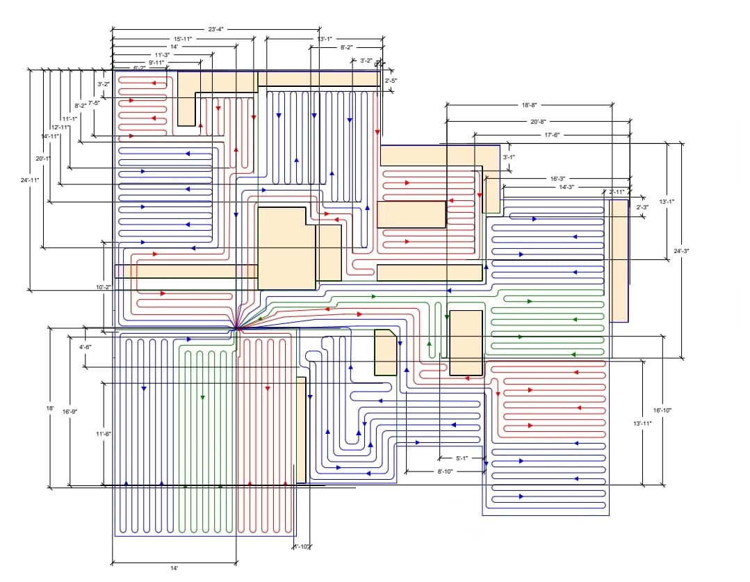
Loops are all right around 300'.
This is the diagram and the picture of the finished product (We ended up skipping the loops in the garage).
 0
0 -
If you get rid of the mixing valve, then you will have 180° water left over after the DHW cycles, entering the radient system,
Which is a safety issue
0 -
This is a double tee, so that we have primary/secondary loops
The primary pump isnt "fighting" anything, it's circulating back via the tees
0 -
That is absolutely NOT primary/secondary piping, that is a bypass and the boiler circ is pumping directly at the mixing valve. Also can you please explain the "safety issue" of 1 quart of 180 degree water hitting the radiant floor?
2 -
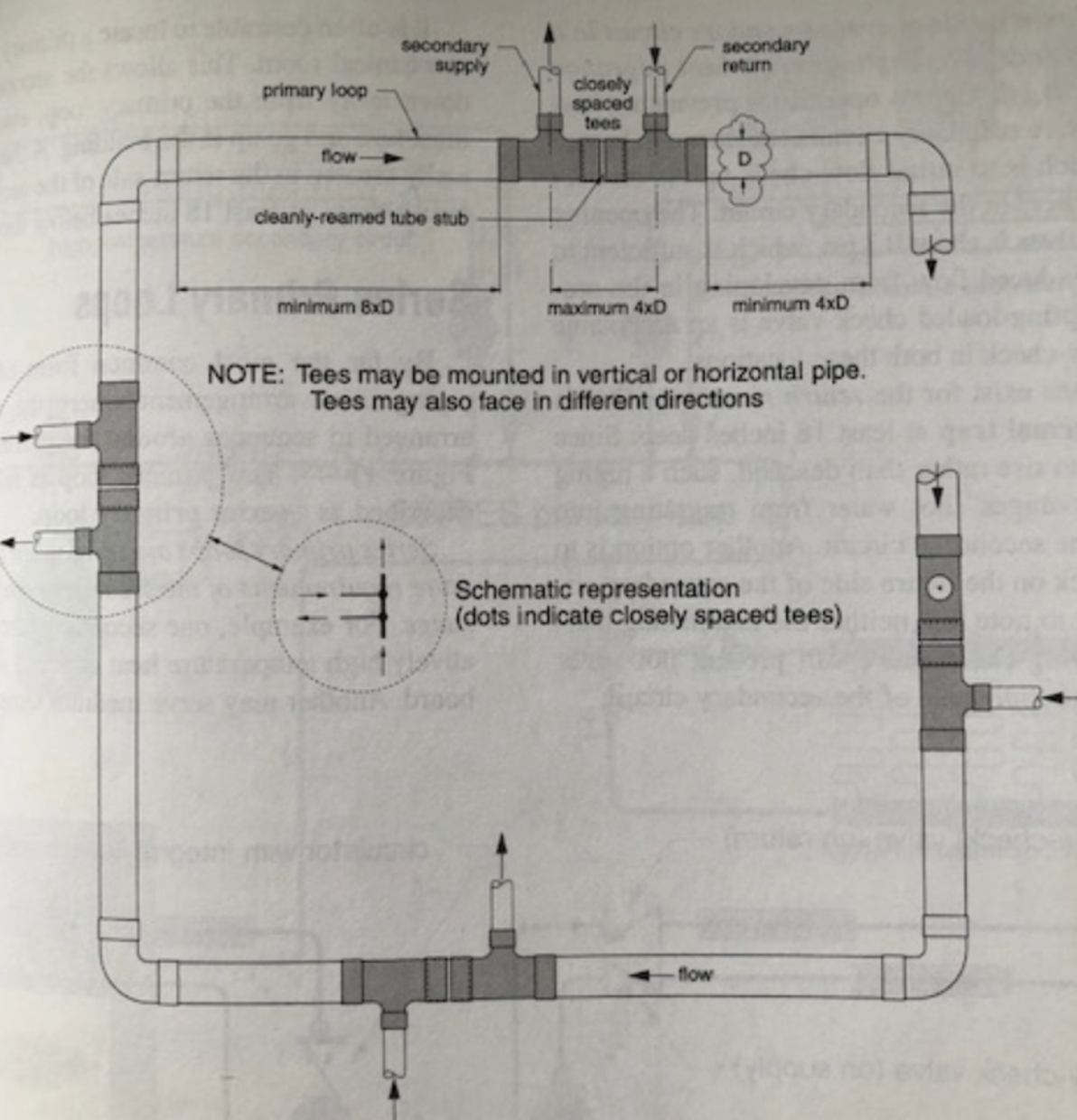
Here is an example of a primary secondary, you want to have some straight section before and after the tees.
While that crossover does establish a boiler loop, I don't think you are getting hydraulic separation between the boiler pump and radiant pump.
If this is a one temperature system a small amount of repipe could get you a boiler loop, indirect as a parallel loop, and a secondary loop with the correct spacing.
The primary loop is defined as the one with the expansion tank connected, it could be the boiler loop, the radiant loop, even the indirect loop, depending on the piping.
 Bob "hot rod" Rohr
trainer for Caleffi NA
Living the hydronic dream3 -
Your diagram of the tube layout is poorly done in my estimation (climate dependent, of course) . Your serpentine layout isn't how I would have design it. I like to put the hottest water next to the exterior of the building and the cooler water toward the interior. The colder the winter outdoor temp, the more important I think layout is. But, what is, is. There is a lot to hydronics.
buildhouse, I give you and your friend an 'A' for the job that you've done. I like the fresh look of your installation even tho it could have been done better, except for the paint cans.
You got a lot of great information on this forum and I know it will be helpful.
0 -
Good Eye! I didn't see these tees, even with your Arrow it was hard for me to see that. It does look like there is a component of hydraulic separation there but not the typical layout of primary/secondary.
I agree with you, persistent flow 180F water in the floor would be bad. I found a manual for the Noble (not sure its OP exact model) and it does have the capability to control the indirect circulator and change the water temp when DHW call vs floor. In other words, the boiler, cycles the temp back down to 120F (or hopefully lower with ODR) immediately after the DHW call is met.
The mixing valve does add a fair amount of resistance to flow. Even the 1" iSeries ODR mixing valve has a surprisingly low cV. And since the boiler can control that low temp effectively, it makes sense to use it. OP question has to do with return water temps that are below expected and this likely related to below optimal flow through the radiant loops. Getting rid of the mixing valve is an option to improve flow and with the ODR function, improve overall efficiency.
0 -
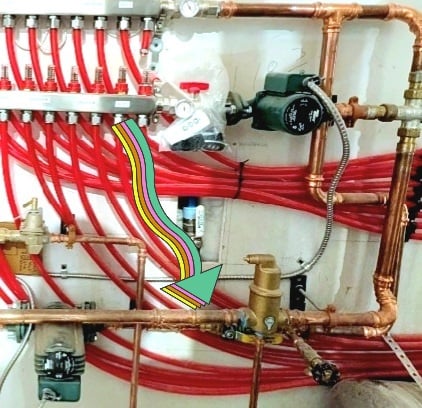
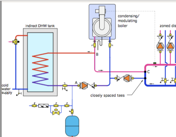
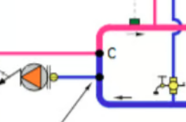
If this is your closely spaced tees, it ain't. I think there are hydrolic problems with that set up. It's a bridge. Look at hot_rod's post out of Idronic at the closely spaced tees labeled 'C'.
I have never seen the connection pictured any other way.
1 -
here are a couple piping fix options with closely spaced tees.
The Nobel, depending on the model is 1.4, 2 or 2.7 gallons of water content. Sending that to the radiant after the indirect satisfies will not be noticable. The Pex is rated for the 180f
 Bob "hot rod" Rohr
trainer for Caleffi NA
Living the hydronic dream1 -
Exactly!
0 -
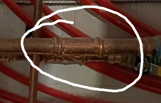
Here are some pictures that might show it better.
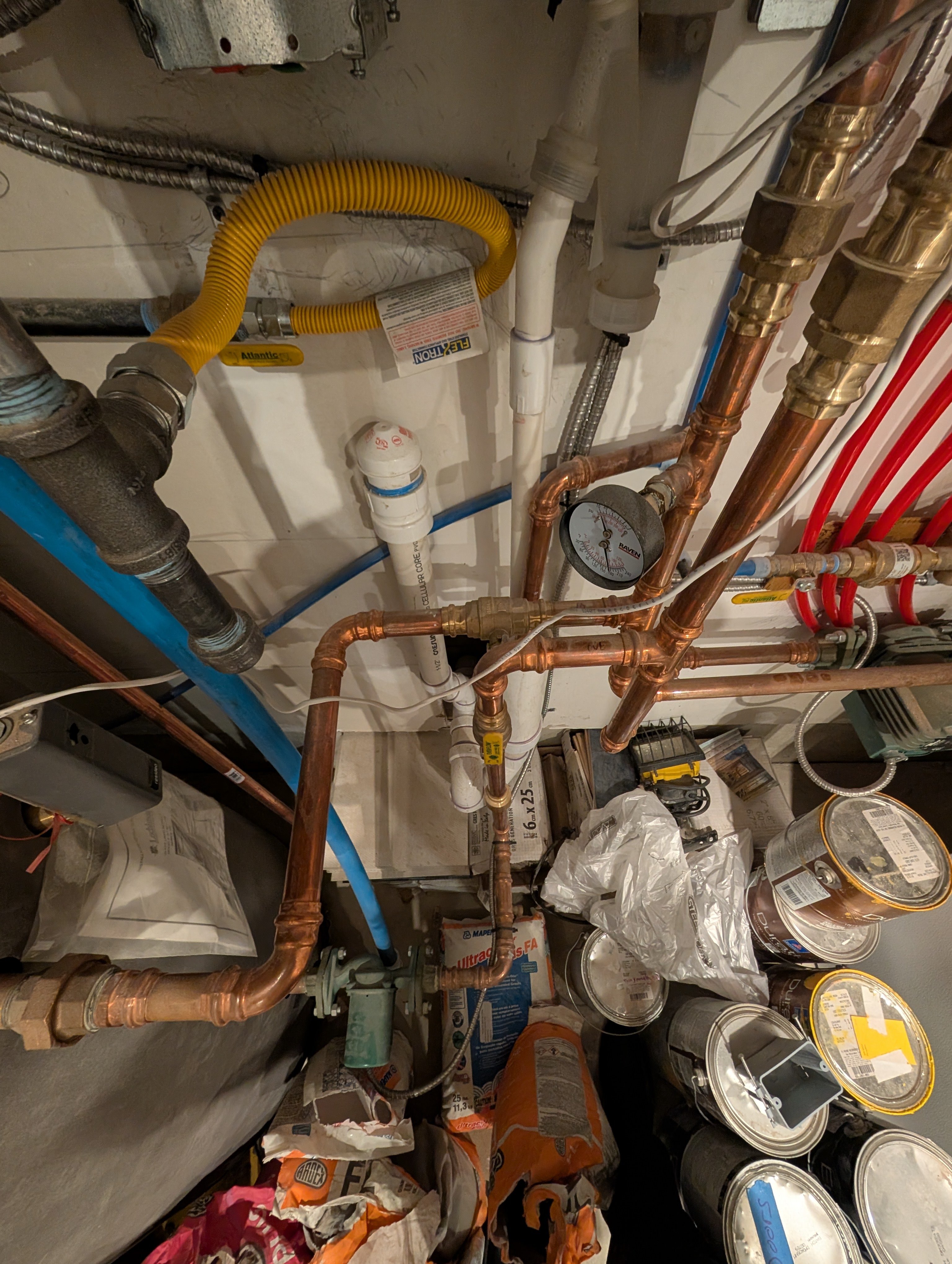 0
0 -
Water will take the path of least resistance. For the boiler pump and loop, that path is across those tees back to the boiler. The pressure drop thru the 3 way is much higher. I predict some, maybe most of the boiler flow crosses those tees and makes a "primary loop".
But the bigger issue with that tight H connection is the pumps are not completely isolated from one another in a hydraulic sense. So a % of the boiler pump is probably going to the zones with the zone pump.
This just isn't the correct way to pipe it no matter how many ways you look at it :)
As mentioned you could get two birds with one stone here. Get rid of the unnecessary mix valve and get the piping corrected to a workable P/S
Hack saw the H assemble out move the spiro back and make one of the two loops I have shown above.
Is that the correct pump on the boiler loop? What size Nobel? the manual will tell what the correct pump options are.
A stick of copper tube, a handful of press fittings and this is a days job or less.
Bob "hot rod" Rohr
trainer for Caleffi NA
Living the hydronic dream2


Categories
- All Categories
- 87.7K THE MAIN WALL
- 3.3K A-C, Heat Pumps & Refrigeration
- 59 Biomass
- 430 Carbon Monoxide Awareness
- 129 Chimneys & Flues
- 2.2K Domestic Hot Water
- 5.9K Gas Heating
- 122 Geothermal
- 170 Indoor-Air Quality
- 3.8K Oil Heating
- 79 Pipe Deterioration
- 1.1K Plumbing
- 6.6K Radiant Heating
- 396 Solar
- 16K Strictly Steam
- 3.5K Thermostats and Controls
- 56 Water Quality
- 51 Industry Classes
- 51 Job Opportunities
- 17 Recall Announcements