Large radiator system (60+ radiators) with one anemic zone

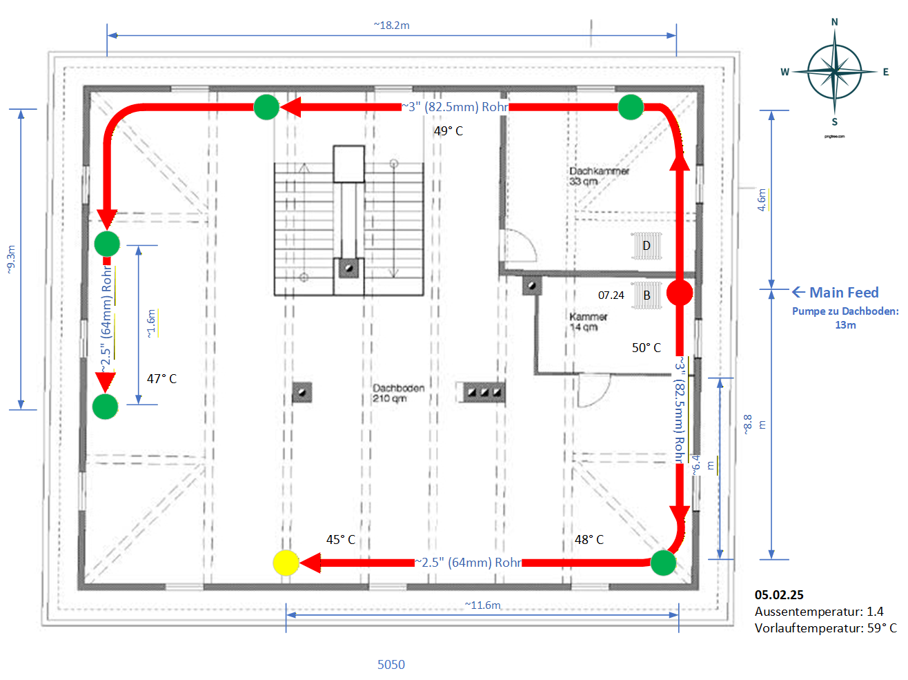
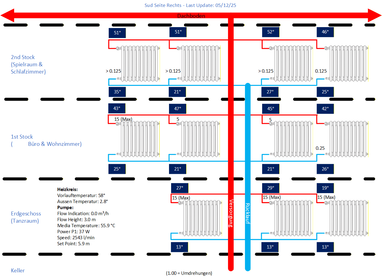
I have a large radiator system (60+ rads, wood pellet furnace) across three floors. Building is located in Germany and over 300 years old. Rad system was probably installed in the 1970's. Furnace was replaced in 2021. The heated water is pumped from the basement to the attic and then distributed across 6 "zones" where it drops down to feed the rads. I have been in the process of removing the rads, flushing them and replacing both the lockshield valves and thermostat valves with new units that allow me to more precisely control the rate of flow through the rads. Everything has been balanced to the best of my abilities. The problem is that one zone, in particular, is always anemic relative to all the other zones (Figure 1 shown in yellow). If I shut off all the rads in that zone (Figure 2) but the bottom floor rads, they do heat up so I know that flow can get down there. I replaced all the insulation on the distribution pipes in the attic this summer and discovered that the pipe diameter feeding that zone is smaller and runs longer (11.6m) than the rest of the other zones. There is a small diameter run at the end of the other distribution pipe but it is 1.6m long. So I think I have two possible routes to try and address this:
- Replace stretch of 11m pipe to the anemic zone with larger diameter pipe. Leave a 1.6m small diameter section to anemic zone to match other end of distribution pipe. This should allow more equal distribution across all the zones but will require rebalancing and maybe a bigger pump.
- Replace present pump with a bigger pump to overcome resistance to that zone. Brute force approach.
Are there any other options and/or recommendations? Any downsides I am missing?
Comments
-
Could you install some ball valves where the supply pipe meets each zone? If so, you may be able to balance the amount of flow to each zone. In this case start to partially close the valves to the warmer zones and see if the cooler zone becomes warmer…
0 -
Was the pump sized correctly for the required gpm and head? If so then it is still a balance issue.
Todays high efficiency circulators give you a lot of flow options with the ECM motors.
A local Grundfos or Wilo person should be able to help with proper sizing.
Bob "hot rod" Rohr
trainer for Caleffi NA
Living the hydronic dream0 -
Yeah that is the big question. The pump (Biral ModulA 40-6 Red) is running at close to max delivery height setting in proportional pressure mode. I tried running in constant pressure mode but no difference. Not sure I can squeeze the flow down any further on the other zones and keep the delta T within 10 to 20C on the rads in those zones. The motor was replaced before my time so I can't say whether it was sized correctly or they just swapped in another motor of similar size, which may have been undersized to start with. It looks like there were some additional extensions done to some zones over time, which may not have been accounted for. You are looking at 13m from the pump to the top of the distribution pipes.
I'll see what the local heating systems guys say. The challenge is that is is a really big system and I need to find someone that has experience with this at this scale.
0 -
When I was redoing the distribution pipe insulation I was hoping I'd find some ball valves but no such luck. That would be a lot of cuts/welds to make in the pipes versus replacing one section of pipe and/or swapping in a bigger pump.
0 -
A system of that size would generally have multiple balance valves. Valves on the branches, fine tune valves at each heat emitter. The lock shields offer that fine tuning, but getting all the branches balanced first assures all the long and short runs get the exact flow they need.
With a building with un-know piping, getting a proper balance is not so easy.
But as you noted the proper sized circulator is a must.
What part of Germany? We have some excellent Caleffi people in Germany.
Balancing and valve selection is a pretty involved topic, some reading here.
Bob "hot rod" Rohr
trainer for Caleffi NA
Living the hydronic dream0 -
Interesting article. There are no ball valves to be found. It's all straight piping unless they hid them in the stone walls. I did some quick back of the napkin math to get a rough estimate on the meters of head I would need based on the longest run in the system. If I do not take into account the 13m up/down feeds I get roughly 3.86m of head required. If I do account for the 13m up/down feed I get 5.4 m of head required (max distance * 1.5 *.04). Had to do some back and forth feet to meter conversions to use this formula since it's based on feet. The pump (which I can interrogate via Bluetooth) on its max proportional pressure setting says it is delivering 3m of head. If I change the profile from proportional pressure to constant pressure at max setting it jumps to 6m head (max rating for the pump) but the power consumption goes through the roof (100W vs 38W). I can adjust the constant pressure profile to change the meter of head being delivered to something between 3m and 6m but it just consumes more power to do so. Given this is such an old system maybe proportional pressure is not the way to go.
0 -
this issue explains the differences between those two settings. I don’t see a way around increasing flow without increasing the power consumption?
But if the system is out of balance, just increasing the flow may not be the answer.
Typically we would have automatic balance valves on those 3 branches designed for the total gpm of the radiators on the branch, a PIV pressure independent type balance valves, then use the valves at the radiator for additional adjustment. If you have TRVs on each radiator.? Those will help with flow control and temperature regulation.
If you cannot add some additional balance valves you will need to adjust pump to the longest circuit and keep adjusting radiators. The correct pump setting may take some trial and error.
Bob "hot rod" Rohr
trainer for Caleffi NA
Living the hydronic dream0 -
TRV's on all the radiators with refurbished units having a built in adjustable flow control. On older units I have to control flow at the lockshield valve. Somewhat crude. I may try slowly increasing the constant pressure setting and see how it affects the system as a whole. You asked about location. I am in Bavaria just outside of Munich.
I do have a question, would a larger pump be able to increase flow, say to 5m of head but not consume as much energy as a smaller pump trying to do the same. I know there will be an energy consumption increase either way but would a larger pump be more efficient at it versus the smaller pump?
0 -
If you are talking about ECM type circulators, I doubt there is much more efficient pump than this.

Larger pumps sometimes have efficiency curves in their spec sheets.
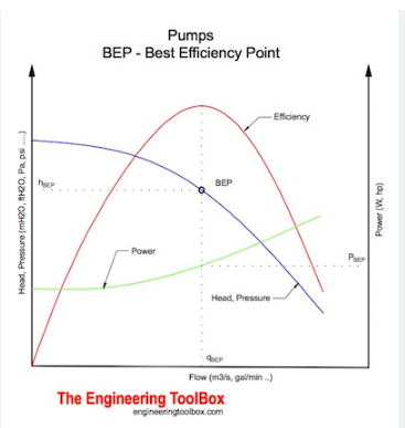
BEP best efficiency point. ideally you do not want to run a pump at either extreme end of it's curve. It would look like this.
Plenty of You Tube videos explaining BEP.
At some point you don't want to trip over watts at the expense of occupant comfort?
Bob "hot rod" Rohr
trainer for Caleffi NA
Living the hydronic dream0 -
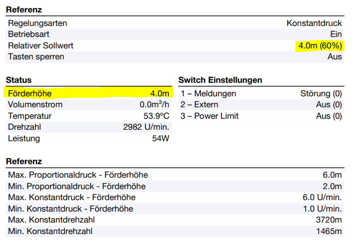
I'll just pump up the meter of head incrementally and see how the system behaves over a couple days. Need it to get cool again. We have a warm front on us for the next week. It's presently reporting 4m of head being delivered. I can't make any major changes until the spring anyway.
 0
0 -
You could install a small adjustable pump on the low flow loop like:
This can be plugged in to run all the time and flow rate adjusted to get the temps you want. You can also wire it to local thermostat for better control.
0 -
Interesting suggestion but I'd have to draw power into that section of the attic where there is none.
0 -
Where in attic was /is the open to air expansion tank or was it removed??????????????????????????????????????????
0 -
No open air expansion tank. It's a closed loop system. Expansion tank is located in the basement.
0 -
Was your heating system a bottom fed steam heating system with a hand fired boiler using lignite coal at one time or a gravity fed hot water system?
What type of tank does your system utilize?
Is it a steel compression tank that hangs between the basement ceiling joists or a bladder tank that sits on the floor?
How many gallons in capacity is it?
It is entirely possible your systems point of no pressure change is not large enough which would cause your system to be anemic, and adding a second steel compression tank with an airtrol valve or a second bladder tank connected to the first one would solve this by adding additional pressure to create the correct amount of no pressure change resistance.
0 -
Diaphragm Expansion Vessel that sits on the floor. Made of steel. 400 liters. Pressured to 1.8 Bar. Prior to the Wood Pellet furnace it ran on a heating oil furnace running on same pipe infrastructure. Prior to that I suspect it might have had a gravity fed system. There are a pair of old pipes leading up to the attic (dead) and what looks like some sort of lifting mechanism on of the attic beam above/near the pipes. Switching Proportional Pressure to Constant Pressure and pushing the Meter of Head from 3.0 to 4.2 on the pump seems to be improving the situation. The bottom rads in the anemic zone are actually starting to get warm even on the colder nights which they never did before.
 0
0 -
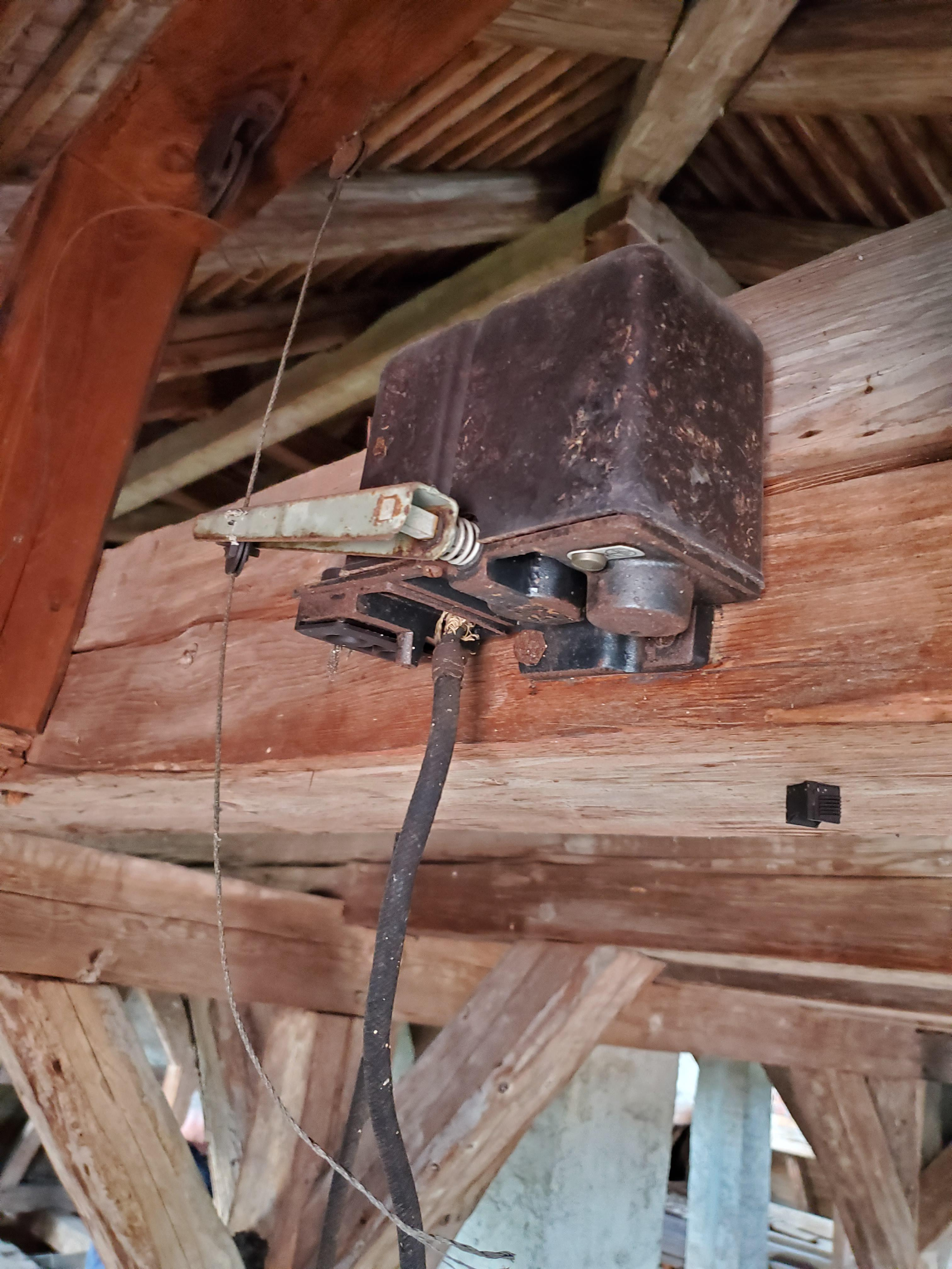
I believe it is a shutter motor draft control for the old hand fed. The shutter motor has a grooved sheave wheel which pushed up and out on the wire cable to open the heavy draft damper door of the hand fed boiler in the basement.
You may still be able to see a sheave pulley over the space where the hand fed boiler was.
0 -
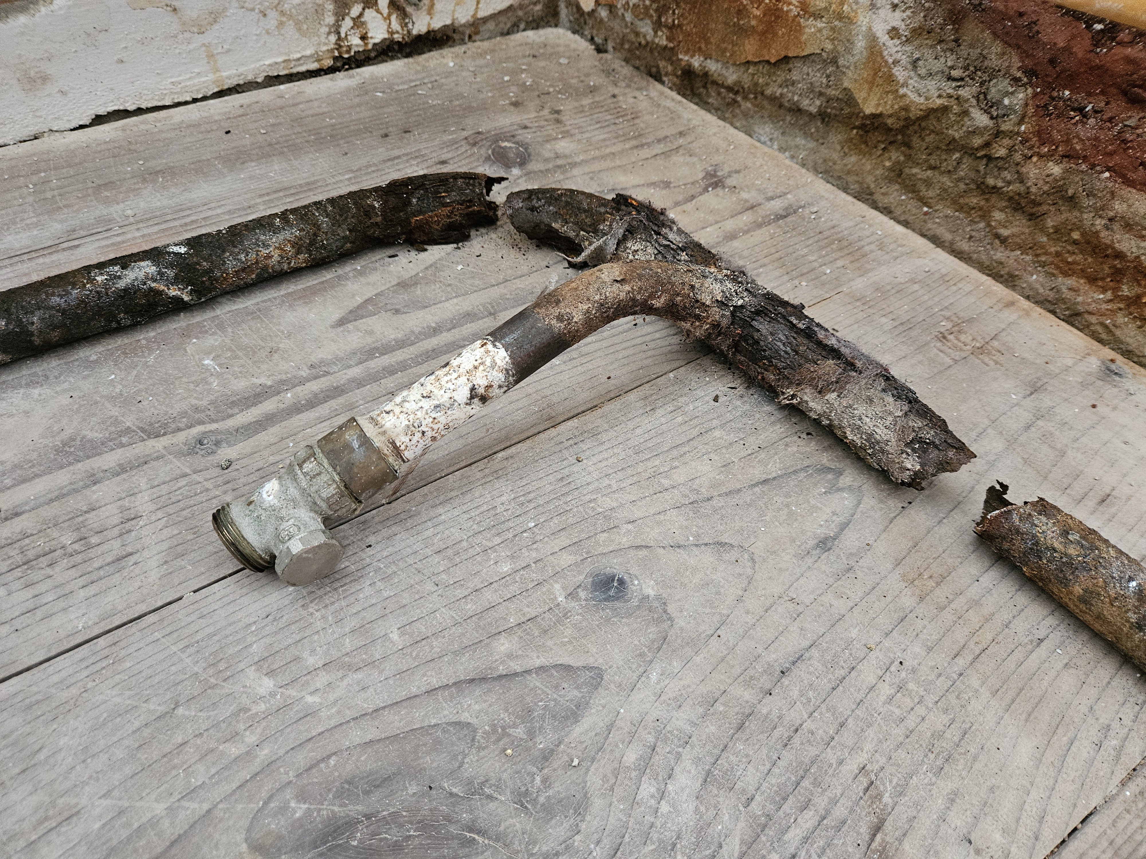
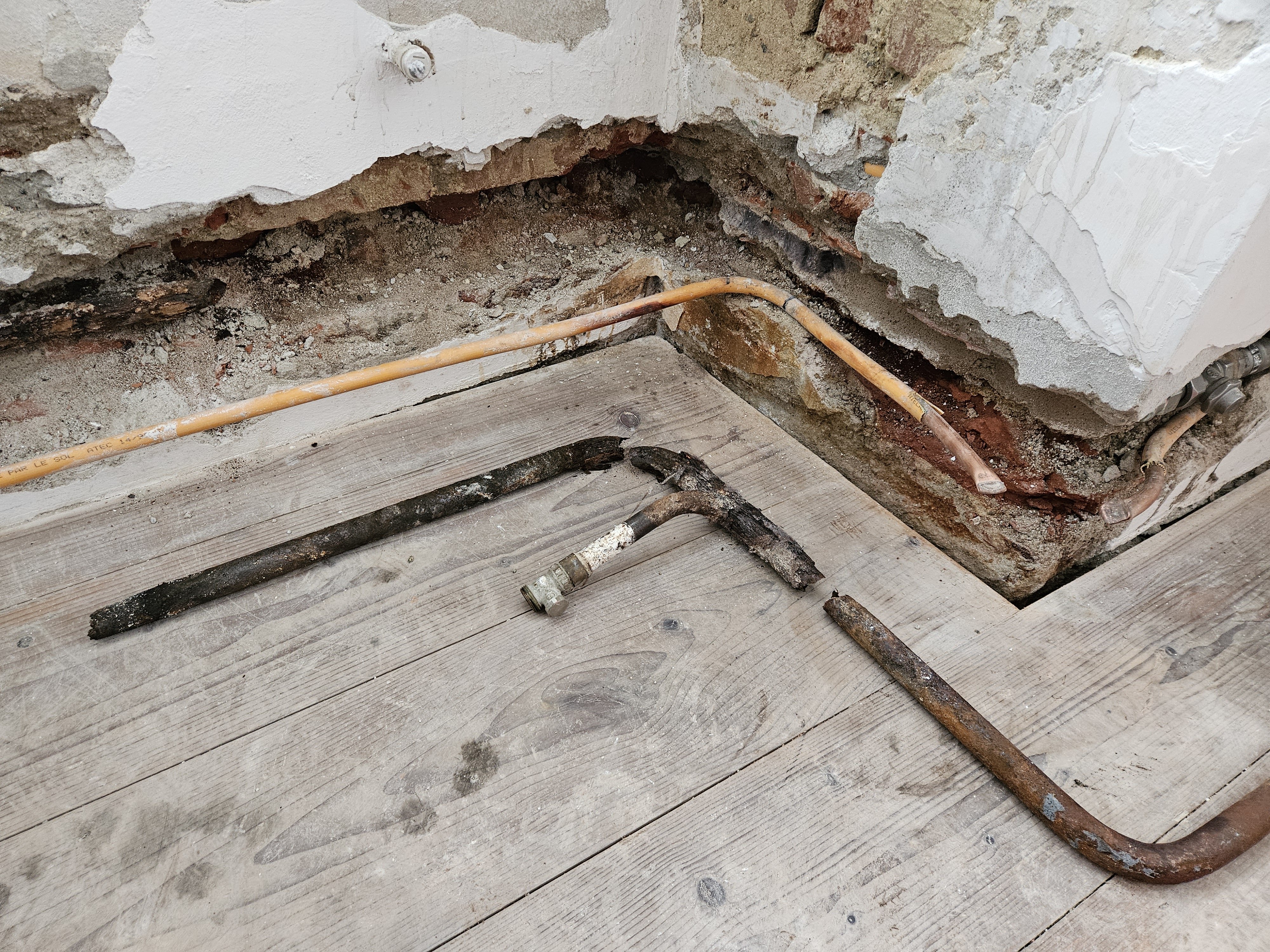
So, major update on this issue. Increasing the meter of head definitely started pushing more heat to the weak zone radiators, but I noticed I was constantly loosing pressure and having to add more water to the system. I've always had this issue and attributed it to system loss but it increased substantially over the last couple of weeks. There was no moisture coming out of the pressure relief valve and the expansion diaphragm pressure was fine so I had a water leak somewhere in the system. Started checking all around the building and noticed a small moisture spot in the wall downstairs. I decided to chisel out the wall to see what was going on and as I got closer water started trickling out. Then, it let loose and water came rushing out. The pipes were totally corroded through. The only thing holding them together was the cement surrounding them. Managed to cut/cap-off the corroded pipe supply, refill the system and restart. Since then the whole system is working substantially better. No pressure loss at all and operating between 1.8 to 2.0 bar consistently which it never did before. The leak was probably always there, perhaps for decades, but pushing the meter of head seems to have worsened the situation. I still think the long section of smaller diameter pipe to the weak zone upstairs is not optimal, but not enough to replace it at this time.
 1
1 -
If the soil around that copper is ever wet, or even moist that can accelerate corrosion. The soil type has a lot to do with copper corrosion also. Consider either wrapping the copper, or use pex.
We had one subdivision where copper K service water lines were pin holeing within a few years.
Turns out the whole area had been a mine tailing dump years and years ago. The aggressive soil would eat up the copper. It ended up being a Superfund project where the top layer of soil was scraped off, taken to a hazard waste disposal and fresh soil brought in.
But water lines were 6' deep in this mountain climate!
Bob "hot rod" Rohr
trainer for Caleffi NA
Living the hydronic dream0 -
Have you given any thought to adding a buffer tank in the attic to increase the amount of thermal mass and gallons of hot water by creating a gravity fed system that is pump fed with a float switch to prevent surges if the tank is vented?
0 -
The pipe that burst I believe is made from "black iron". The copper pipe you see is part of a secondary system that is supposed to heat the walls to reduce moisture. It probably hasn't been used in decades. The pump that powers it was corroded solid when we moved in 5 years ago. When I get new replacement pipes installed I'll try to bring that system online as well. It's probably a contributing factor for all the corrosion you see. That and there wasn't any type of protective insulation around that segment of pipe so it was exposed to all that moisture for decades.
1 -
it’s cool the way the pipe are commonly bent and shaped to fit in Europe. I imagine it save a lot of time during installs once you get the hang of it.
0 -
Definitely minimizes the number of possible joint failures when it's one continuous run.
1


Categories
- All Categories
- 87.7K THE MAIN WALL
- 3.3K A-C, Heat Pumps & Refrigeration
- 59 Biomass
- 430 Carbon Monoxide Awareness
- 129 Chimneys & Flues
- 2.2K Domestic Hot Water
- 5.9K Gas Heating
- 122 Geothermal
- 170 Indoor-Air Quality
- 3.8K Oil Heating
- 79 Pipe Deterioration
- 1.1K Plumbing
- 6.6K Radiant Heating
- 396 Solar
- 16K Strictly Steam
- 3.5K Thermostats and Controls
- 56 Water Quality
- 51 Industry Classes
- 51 Job Opportunities
- 17 Recall Announcements