New Installation Circulator Flow Problem

Hello All,
Novice Here, Not A Pro, But Mostly Capable.
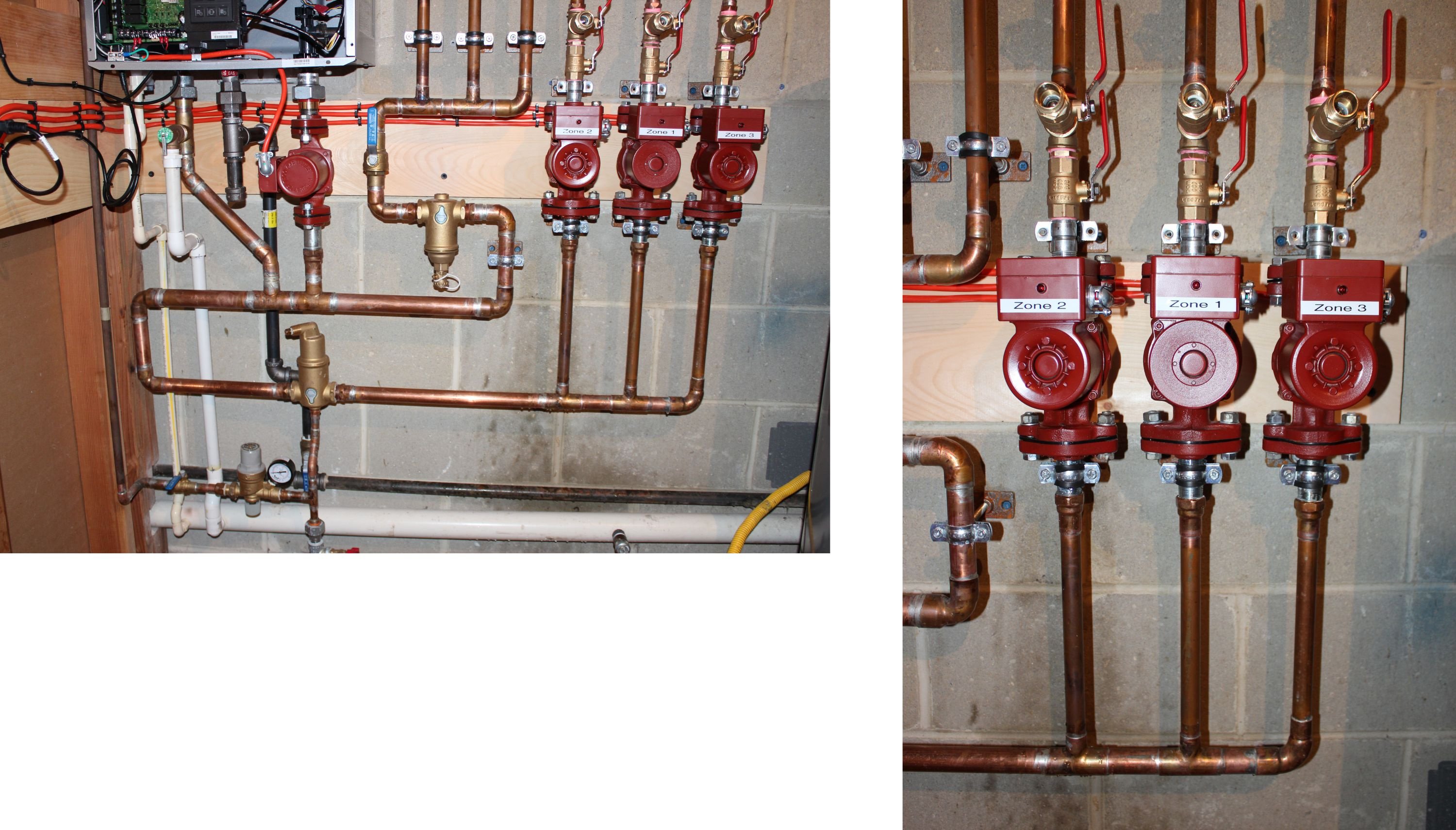
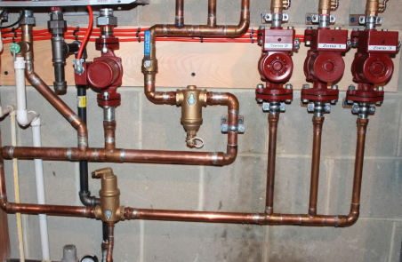
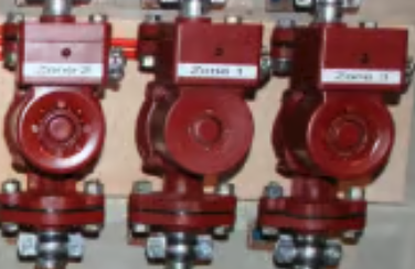
I Installed A New Rinanni i150s Solo Boiler In My Home, Three Zone Each With Its Own Circulator.
Note The Three Circulators On The Right.
Each Has Its Own Internal Check Valve On The Output Side ( Top ) Of The Circulator.
The Are Flow Control Valves For Each Zone Above The Circulators ( Not Shown )
Expansion Tank ( Not Shown ) Is Below The Feed Water Regulator
The Three Returns Are On The Left Of The Circulators ( Blue Valve Handle )
Here's My Problem…
When Any Two Zones Are Running And I Attempt To Start The Remaining Zone,
I Get No Flow Through It, I'm Guessing Because The Suction From The Two Running
Pumps Are Keeping The Remaining Circulator's Check Valve Closed, And The Remaining
Pump Can't Supply Enough Pressure To Open It's Own Check Valve.
Tried Removing The Springs From The Check Valves…No Joy.
Tried Removing All three Check Valves And I Get Good Heat All Three Zones.. But I'm Guessing
That's Not A Good Permanent Fix ( Comments On That ? )
I'm Sure I Missed Something, And I'm Hoping You Kind Folks Can Educate Me.
Comments
-
Removing the check valves may give you heat in zones where you do not need heat. You can get ghost flow.
Piping looks good. But where is your expansion tank connected and which direction are the pumps pumping and which is supply and return fom the boiler?
0 -
Thanks For The Reply…
Expansion Tank Is Connected To The Bottom Of The Auto-Fill ( Just Below & Right Of The Pressure Gage)
Supply Enters The Bottom Of The Circulators, Returns Are The Three Pipes Connected To The Blue Valve
To The Left Of The Circulators.
Regards,
Bill
0 -
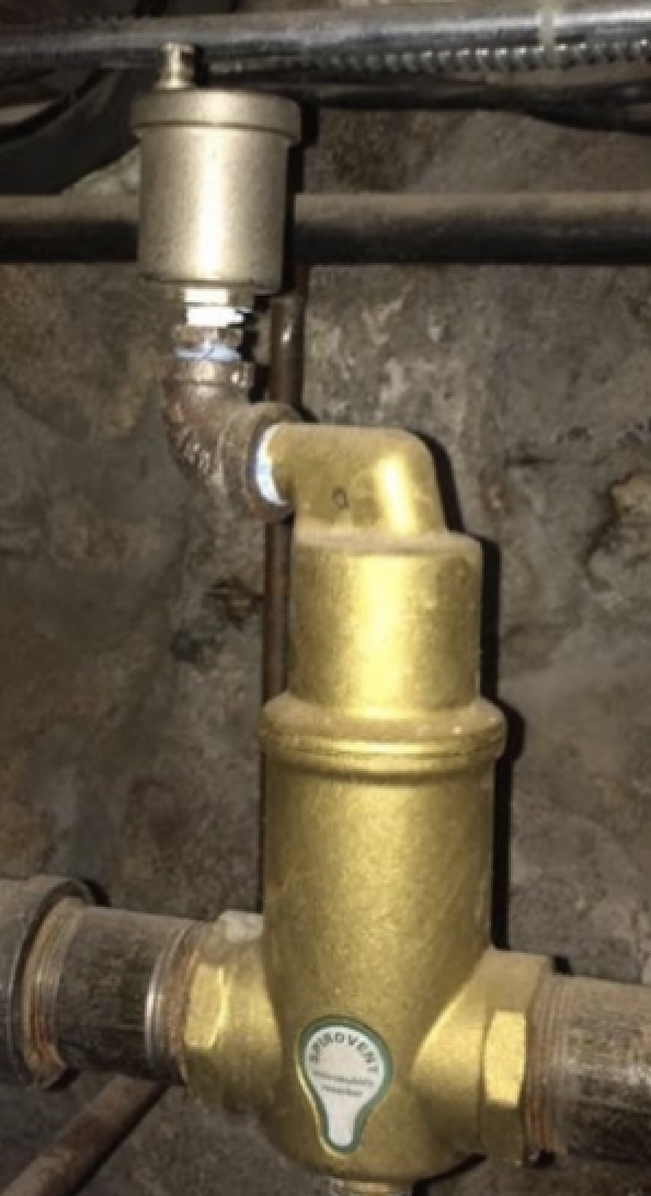
Is it a threaded brass plug in the air separator or is that the regular air release fitting that comes pre-installed?
0 -
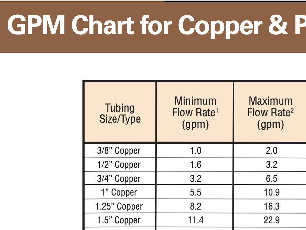
The pipe size supplying the 3 pumps needs to be large enough to handle the gpm requirement when all 3 are running.
Looks like you have a 1" trunk supplying 3 circs? Maybe a piece of 1-1/4 thrown in :) under the boiler?
That may be adequate to keep any or all flowing their required gpm.
But if each zone pump needs 4 gpm, or more, 12 gpm total, the 1" is a bit undersized. Do you know flow requirements on the 3 zones?
8 maybe 10 gpm on 1" copper M
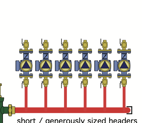
Best practice the "header" is sized for total gpm at 2 fps velocity, aka "fat" headers. Column #1 on the chart below is flow at 2 fps.
Those look like Vevor knock-off circs, are they 3 speed? If so try all on speed 1, that would confirm the suspicion.
 Bob "hot rod" Rohr
trainer for Caleffi NA
Living the hydronic dream1 -
Why are you reducing the size of your manifold? Because you have the zones connected to 2 ends of a loop instead of with closely spaced tees and an circulator for that loop, the circulators for the zones will interact with each other and my guess is that the pipe between the 2 isn't big enough to give you enough flow with all 3 circulators running, the resistance of one of the loops is similar to the boiler loop so the total head on that pump is more than in can overcome. I think either you need to make the manifold bigger all the way through or you need to use smaller circulators if the head on the loops will allow for that. Are those single speed conventional wet rotor circulators?
0 -
Hello All, Thanks For The Replies…
The Original Boiler ( 35 Years Old ) Had 3/4" Manifold… I Assumed The Original Installer Had It Right And
Just Coupled It To The Rianni.
Rianni Wanted A 1-1/4" Close Spaced Tee Manifold… So That's What I Did.
Went Down To 1" To The Air Separator And Dirt Separators Because I Had Those On Hand & Both Were 1".
The Circulators Are Grunfos 3 Speeds ( Name Plates Off ) … I Replaced The Connector Boxes ( Original
Covers Were Missing ) With My Own To Include A Led So I Could See Which Ones Are Running.
There Is A Temporary Plug In The Air Separator Because It Was Dripping. I Stupidly Tried To Unscrew The Air Vent To Clean It And Ruined The Little Spring Inside.
FWIW The Proper Procedure Is To Remove The Top Bell, Unbend
The Wire That Holds The Floats, Remove The Floats, And Unhook The Spring / Seat From The Inside, Then It
Can Be Unscrewed From The Outside And Cleaned. I Found Debris In The Rubber Seat, That's Why It Was Dripping.
The Spring Is A Special Left Hand Wind That Is Unavailable For Purchase. I'll Buy Spring Wire And Wind My
own. ( Spirovent Wants Me To Buy The Entire Bell Assembly $66.00 For A 10 Cent Spring )
Best Regards,
Bill
0 -
Each circulator has an internal flow check, AND each zone has its own flow control valve (Not Shown). Why both?
0 -
The circ in the center looks like a larger motor, is it a 26 series high head? What model is that one. Maybe it is just a different vintage as the others, same size?
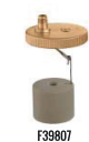
Two fingers disassembles a Discal for service. The cap and valve mechanism is replaceable if the needle or seat is damaged.
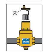
We see a Caleffi fix on that type air purger from time to time :)
 Bob "hot rod" Rohr
trainer for Caleffi NA
Living the hydronic dream 1
1 -
Hello All.. Answers To Comments…
————————————————————————————————————————————————
I Thought I Needed A Flow Control Valve For Each Zone To Better Control Heat Delivered To Each Zone.
Wrong?
————————————————————————————————————————————————The Center Circulator Is An Older Model Than The Other Two.
The Discal Purger Definitely Looks Easier To Service, But The Spirovent Was Free To Me From A Friend.
The Addition Of The Caleffi To The Top Of The Spirovent Seems Like I'm Not The Only Guy With A Leaking Sprovent ( Poor Design? )
————————————————————————————————————————————————-I Learn Best From My Mistakes ( I'm Learning A Lot )
Best Regards,
Bill
0 -
Update…
Problem Solved.
Bad Capacitor On Circulator Pump.
Pump Would Run… But Not Develop Enough Pressure To Open Its Check Valve When Other
Pumps Were Running.
Much Thanks For All The Help.
Best Regards
Bill
0


Categories
- All Categories
- 87.7K THE MAIN WALL
- 3.3K A-C, Heat Pumps & Refrigeration
- 59 Biomass
- 430 Carbon Monoxide Awareness
- 129 Chimneys & Flues
- 2.2K Domestic Hot Water
- 5.9K Gas Heating
- 122 Geothermal
- 170 Indoor-Air Quality
- 3.8K Oil Heating
- 79 Pipe Deterioration
- 1.1K Plumbing
- 6.6K Radiant Heating
- 396 Solar
- 16K Strictly Steam
- 3.5K Thermostats and Controls
- 56 Water Quality
- 51 Industry Classes
- 51 Job Opportunities
- 17 Recall Announcements