Hydronic w/ radiant addition - design question

Background: 50 yr old home, 20 year old oil fired boiler, standard slant fin wall radiators. Recently updated laundry room adding 50 sq ft bringing up to150 sq ft. This area is exposed to the outside on three sides and had ~9' of slant fin radiator. When remodeling switched to 1/2 pex loop under floor in aluminum trays backed by insulation. Total run of 140' of pex.
My math:
I think I need ~7-8k BTUs to warm this space and I think I need ~2 GPM through 1/2" pex and plates to deliver that. Can anyone confirm that is accurate? My head loss through 140' of pex is .27/ft * 140' = 37' that seems massive is that correct before I start looking for a pump that meets this requirement
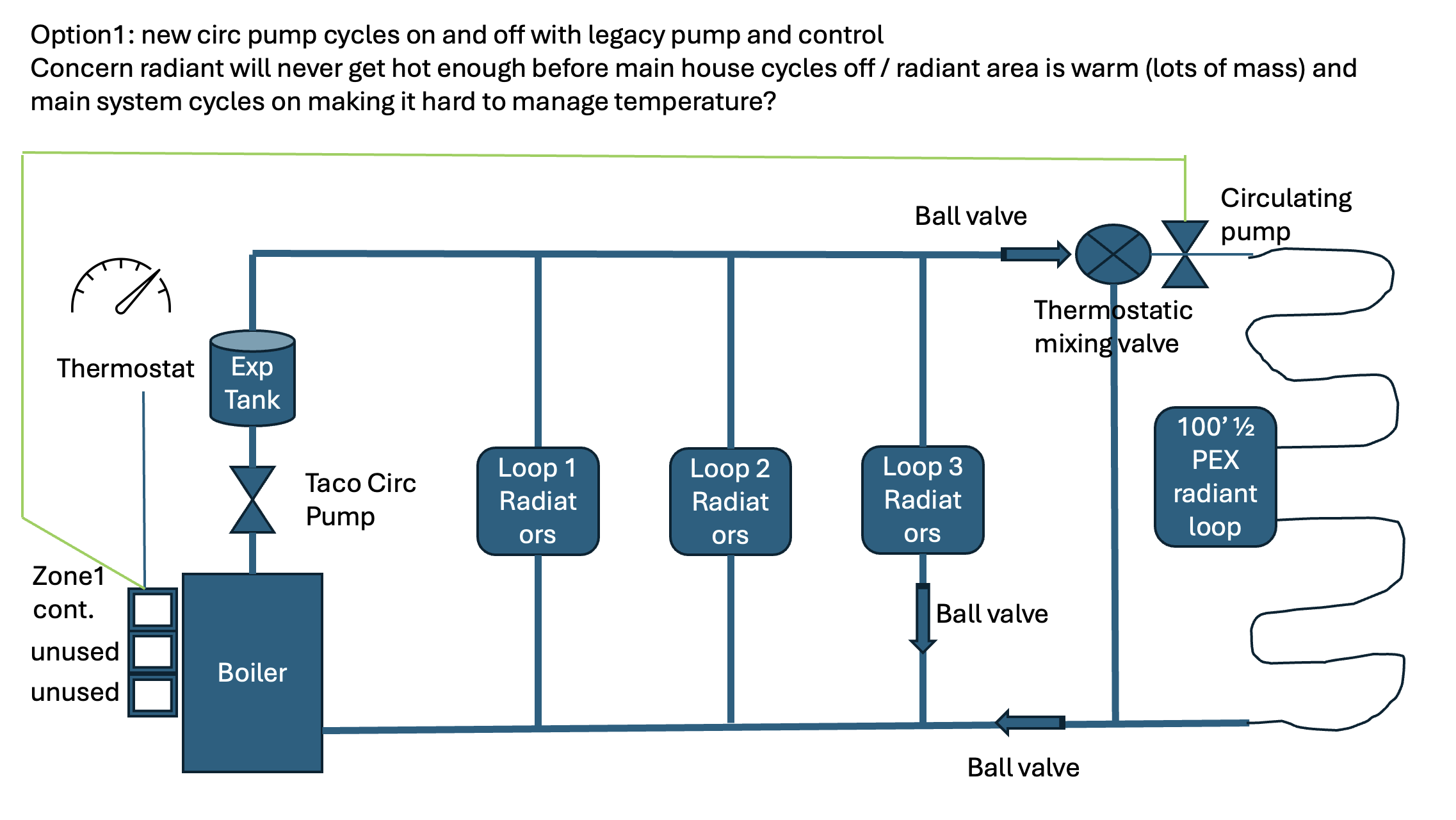
My next question is the layout. I am starting at the end of the run adding a thermostatic mixing valve to them a circulating pump to "push" the mixed water through the radiant loop and then back to the hydronic loop. My plan was to turn the radiant circ pump on and off with the legacy loops to keep it simple. Then I am returning this cooler water to the beginning of the return loop hoping to keep the return temperature above safe boiler return temperature.
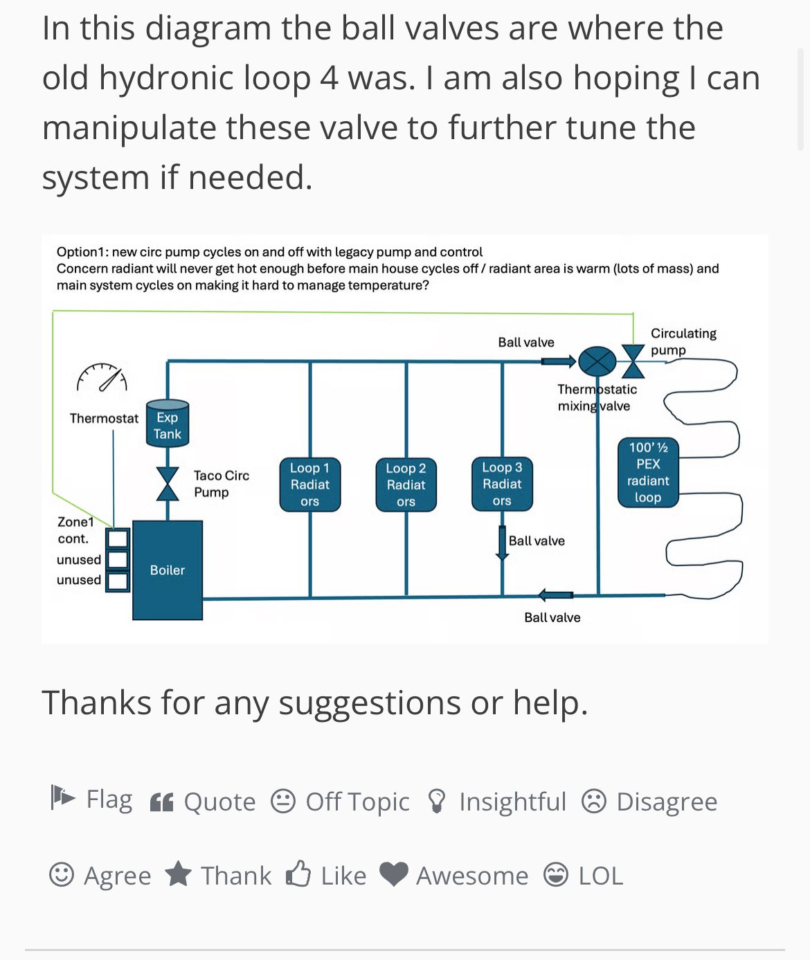
In this diagram the ball valves are where the old hydronic loop 4 was. I am also hoping I can manipulate these valve to further tune the system if needed.
Thanks for any suggestions or help.
Comments
-
If you have 150 square feet and a heat loss of 7,000 BTU/hr, that's almost 50 BTU/hr per square foot. That sounds enormous for new construction. How are you arriving at the 7K number?
Before doing anything I would get an accurate heat loss estimate. Everything else flows from that.
Just as a back-of-the-envelope estimate, a room that is 150 square feet, 15x10, exposed on three walls plus floor and ceiling, would have 150 square feet of floor, 150 square feet of ceiling, and 320 square feet of walls. If the whole thing was insulated to R13— a 2x4 wall filled with fiberglass, which is far below code in most of the US today — at an outdoor temperature of -30F the heat loss would be about 4700 BTU/hr.
I suspect where you are doesn't get as cold as -30F, and I hope you have more than R13 in your walls, ceilings and floors.
 1
1 -
Thanks for the reply and challenging my math I went back and re-did it.
12 x 12 space, 3 2x4 exterior walls insulated with R13, 8' ceiling (insulated with R19 but opens to garage space no occupied rooms above it), ground floor space. Onc "exterior" wall is the garage wall it never gets below freezing in there. Aiming for 68* ambient and down to 0* outside. We rarely get that low but we hang in the high 20s to low 30s. Should I adjust upward my outside temperature? The floor is partially over a 2x8 framing over concrete slab with 2" solid foam and R13 with solid foam all around the perimeter.
The result of this using Omni calculator is 5,326 BTUs / 1,560 watts. If that is correct I am at 5326/144 sq ft = 37 BTU/ sq ft. That sure sounds hot. Before I remodeled this space was heated by ~9' of slant fin but I added 50% more space.
Not important but I should mention floor is 1 1/4 thick (double layer) of plywood topped by travertine tile.
Looking at Pex Universe chart
I have 1/2" pex with two lengths of tube per joist bay - around 8" spacing and it looks like it is good for 22-30 BTUs at .6 gpm but does not consider the transfer plates. At 30 BTU (top value, optimistic, no transfer plates) I am only at 4320 BTU.
Can you verify my math to this point? I do not want a cold space that would be so annoying after all the cost and labor.
Thanks!
0 -
You can find your outdoor design temperature here:
1 -
The formula for heat loss through an assembly is area (in square feet) times temperature difference between the two sides (in F) divided by R-value. That gives heat loss in BTU/hr.
I'm seeing:
288 square feet of walls (36'x8') at R13. With a 68F difference that's 1506 BTU/hr.
144 square feet of ceiling at R19, 515 BTU/hr
144 square feet of floor. I didn't follow your description but I'm going to assume R13 which gives 753 BTU/hr.
Total is 2775 BTU/hr, which is just about 20 BTU/hr per square foot, which is about what I'd expect.
Do you have windows or doors? They need to be added in too.
At 20 BTU/hr per square foot you'd want a floor about 10F above room temperature, or 78F. Since it's a laundry room I'd assume that the washer, dryer and cabinets would take up some of the floor space, you wouldn't want the full floor to be heated, so you'd want a higher temperature for the section that is. So maybe 72 square feet at 88F.
Unless wall space is really at a premium I'd be thinking radiators for this space, it doesn't sound like a space where you're going to be hanging out with your shoes off or lolling on the floor. Five feet of slant-fin would be adequate, as would a 12x24 panel radiator.
0 -
Thanks for running out that calculation this has been very educational. I have a 36" fiberglass insulated entry door (new), 32" hollow core door to the unheated garage (!!) and a 30"x40" double hung insulated window (new) also adding to my heat loss. Looking at the design temperature for eastern PA it is 16*. Can you give me an adjusted total BTUs? I see now how important that is to the calculations I need later.
Between the washer, dryer, sink, cabinets, doors, I only have a very short 3' section of unused wall due to the layout. I am committed to radiant heat - the tubing was all laid under the floor during construction.
The whole 144 sq. ft. floor is plumbed with 1/2" pex to be heated (it is but some under cabinets/appliances) I did that so the plumbing in the area would not risk freezing and my max heat loss is at the walls.If I understand this process
- Calc BTUs needed
- Calculate heat transfer needed from pex and tray
- Determine input water temperature (160* from boiler but mix valve should lower it to under 120 to avoid damage to floor and feet) to determine the energy shift to the floor needed to provide that BTU/sq ft
- Determine the gpm of water needed to provide that energy transfer
- Determine the head loss (mixing valve+plumbing)
- Find a pump that delivers that gpm at that head loss
Thanks for you help it is very hard to find a useful resource in this area.
0 -
If the design temperature is 16F rather than the 0F I used, the difference is 52F rather than 68F. So rather than the 2775 BTU/hr I got you'd get 2122.
Let's say you've got 21 square feet of door at R5, 12 square feet of window at R2. The door is 218 instead of 84 at R13, the window is 312 instead of 48 at R13. So add 398 for the two. That gets to 2520.
I don't know what to make of the wall to the garage. Let's say it's R2 overall, but the garage stays around 50F — I'm just guessing. So 96 square feet, 18F difference, R2= 864. So 3384 BTU/hr for the whole room.
You could put a wall mount radiator in the 36" of free wall space and be done with it.
The part of the floor that is covered by cabinets and appliances isn't going to contribute much heat to the room.
0 -
EDIT ***I did not see you updated post when I typed the response below***
Expanding on my math assuming I need 4000 BTU doing some more math:
Flow rate: f=Q/500*(delta t) = 4000/500*(20 degrees) = .8 gpm. If I need 5000 which seems high btus I need 1 gpm.
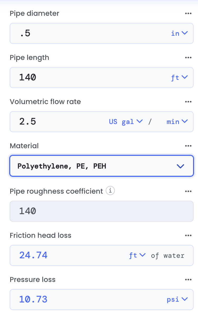
Head loss: calculation I am finding is 3.64 in 1/2" pex at 140 degrees in a 140' run if water.
If that math is correct I need to put 4000 BTUs into the space to. heat it (assuming additional heat loss and reduced exposed area). If I put warm water into the space at .8 gpm through 140' of 1/2" pex I should be able to do that. Can anyone check if that makes sense?
***after reading your post above I am at 2500 BUT but being delivered by floor space only. I need to get the exposed floor space to work out exactly but if it is 100 sq ft then I am in need of 2500 BTU/100 sq ft or 25 BTU/sq ft.
f=2500/(500*20) = 2.5 gpm
At 2.5 gpm my head loss becomes huge - 25 ft does that seem right?
 0
0 -
heat flux, divide the room square footage by the square footage that cabinets or appliances cover. The result is the available radiant panel sq footage that has to cover the heat load
25-27 is a reasonable floor output.
1/2” pex .50- .75 gpm typically
Higher flow rates jack up the head number
Bob "hot rod" Rohr
trainer for Caleffi NA
Living the hydronic dream0 -
Thanks!
Room is 144 sq. ft., non-covered floor is 76 sq ft. If I have 76 sq. ft. of effective radiant area can I get enough BTUs out of it to heat the space? I had been assuming the full 144 sq ft.
Best case of 30 BTU/sq ft * 76 sq ft = 2280 puts me right in range with DCContrarian heat loss calculations. This is assuming .6 gpm. I may need ot slightly increase the gpm to get more output since I am already at the top end of 1/2" pex BTU in this case.
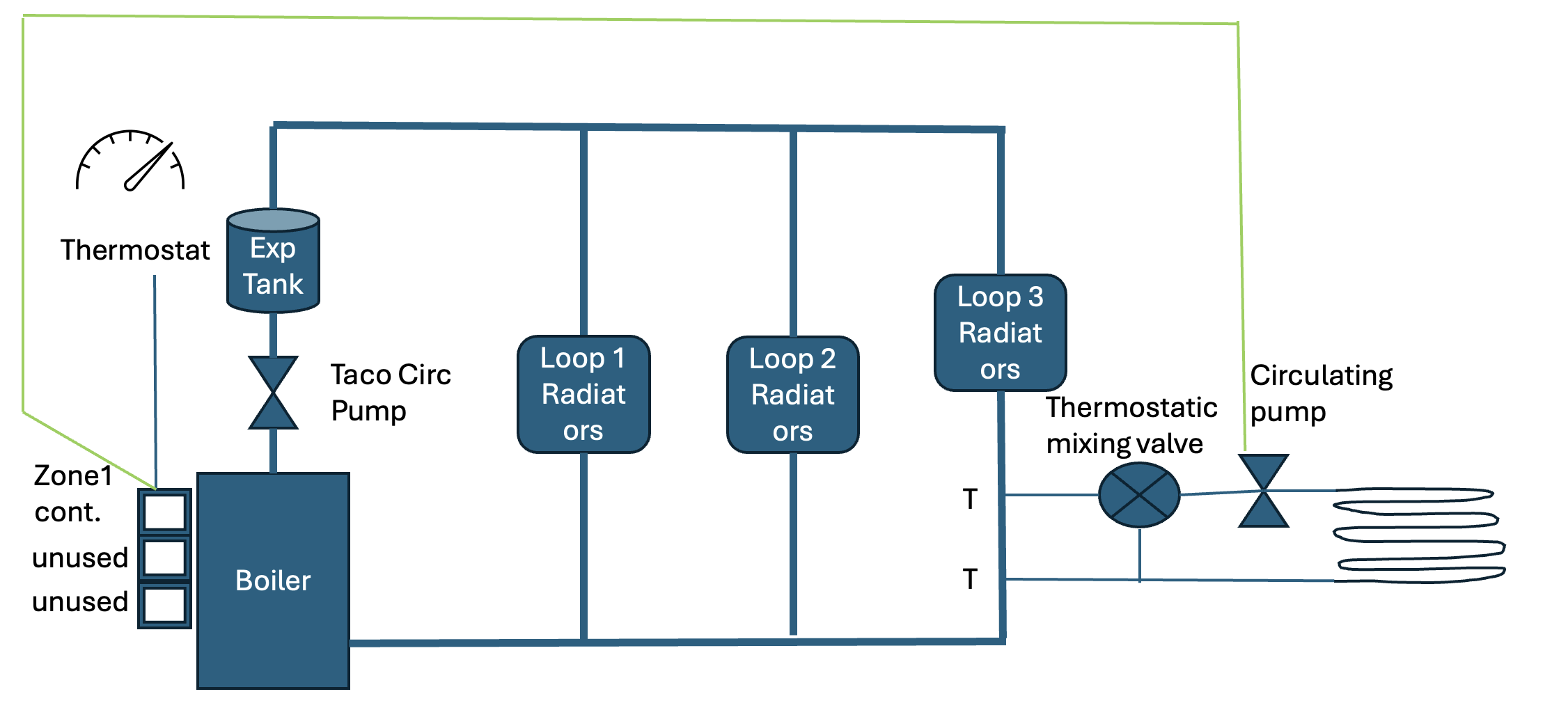
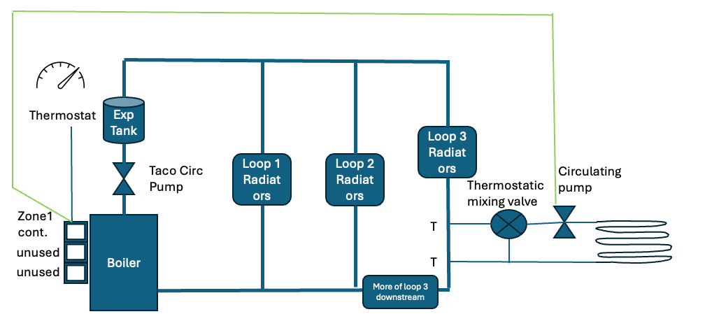
Can anyone look at my diagram and see any flaws? I have the hydronic system supply 160* to the main loops, passing through a mixing valve then a second circulator pump pushing it through the radiant loop. I have both pumps coming with the the same t-stat. Main pump pushes water to radiant loop then radiant pump pishes to ahead. Any excess water can bypass the radiant loop and return. Radiant loop water mixes with hydronic water on the return leg to insure water going to boiler does not get too cold.
Thanks!
0 -
the issue I see is the boiler/ system pump are in series
Anytime the boiler pump turns on for any zone , you may get some push through the mix valve causing that zone to over-heat
There are a few piping options you prevent this
If you google A Little Floor Warming Please Sigenthaler, it is an article on 3 piping options
Bob "hot rod" Rohr
trainer for Caleffi NA
Living the hydronic dream0 -
I was able to find and read that article but the images of the pipe layout are no longer valid links.
0 -
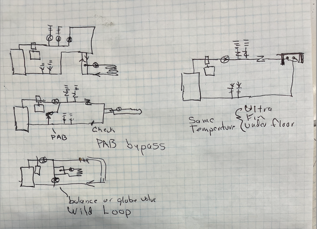
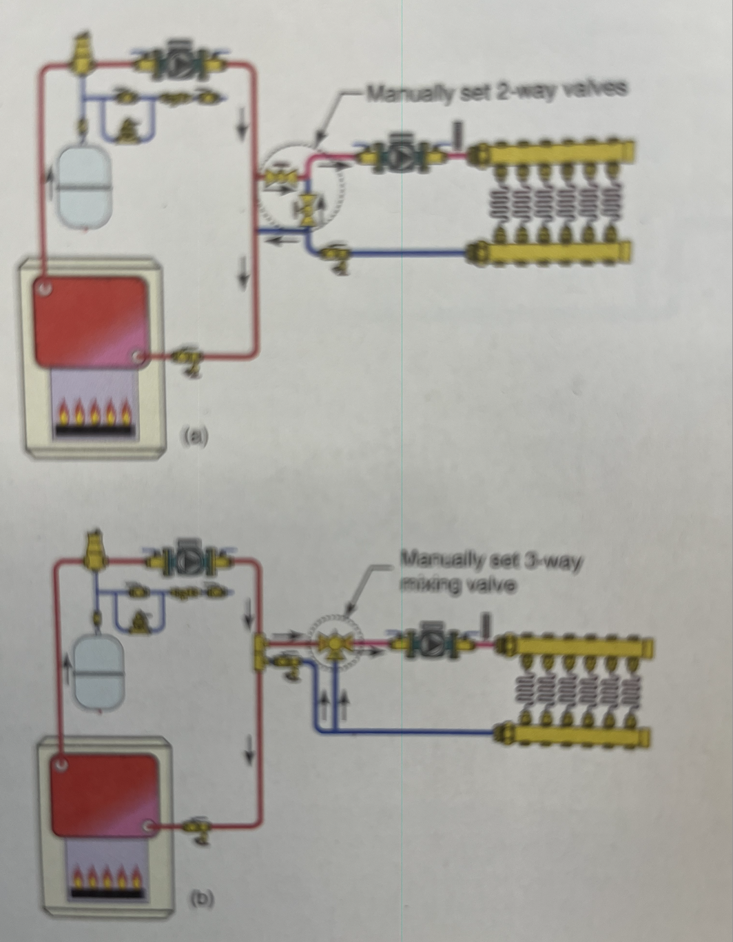
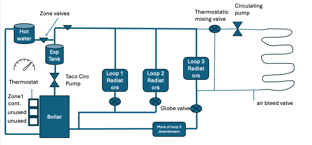
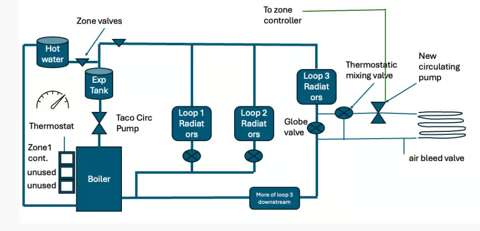
IF you want to run the radiant without any other zone running here are some piping options.
First one builds another loop, needs two circulators to run the loop, then the 3 way thermostatic mix valve radiant take-off from close tees.
#2, used on a system that has a single circ and zone valves. Add another zone valve for a radiant loop via close tees and 3 way thermostatic. Adjust the PAB bypass valve with all high temperature zones calling. There should be no flow across the bypass. as the zone valve close bypass stsrts to flow. Adjust by feel across that bypass pipe. Or a point and shoot thermometer.
#3 "wild loop" typically a single zone system, requires the main circ to be called on. A globe valve allows a small amount of flow across the wild loop, 3 way thermostatic off the close tees. Run the boiler to its high temperature, adjust that globe valve for about a 40° temperature drop across the bypass loop.
The goal with these 3 is to have the mix valve pull of closely spaced tees. This assure it always has a flow of hot supply for the valve to respond correctly.
Option 4 is to use suspended tube or UltraFin and ru it at the same temperature as the rest of the system. this requires access below the floor of course.
These are intended to add a small radiant zone to a high temperature system without repiping the entire system to a primary secondary or hydro sep.
It really depends on how the existing system is piped and how much work to do any modifications.
 Bob "hot rod" Rohr
trainer for Caleffi NA
Living the hydronic dream0 -
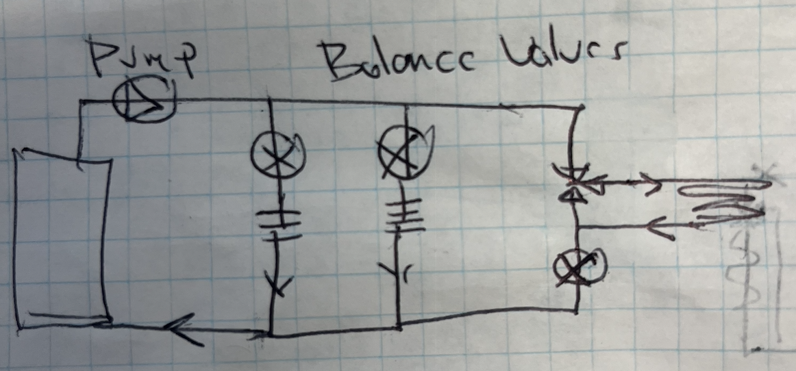
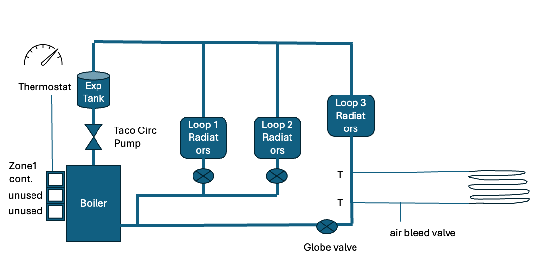
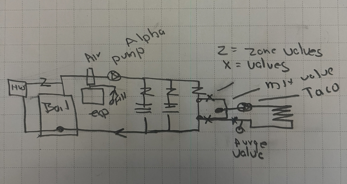
Wow that is a lot of information thank you. I am trying to understand a few of the icons to better understand what I am looking at. I took your drawing and added some call outs if you could confirm. In this design it is basically interrupting the legacy radiator loop.
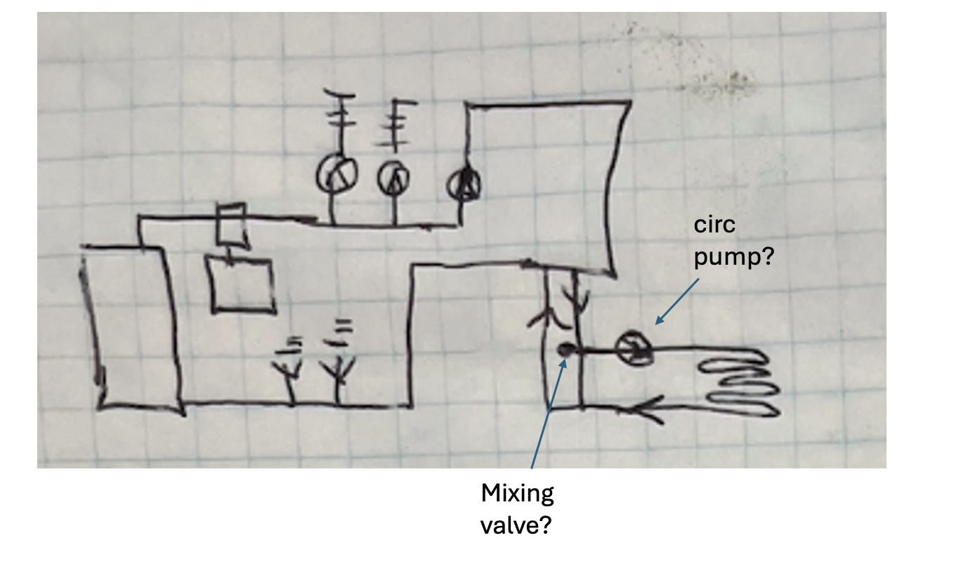
I think my set up is close the first image - basically taping into the hot loop with a thermostatic mixing valve and second circulation pump. I do not understand what "close tees" mean. I was thinking it is best to add my cooler water (after radiant) as far away from boiler as possible so it can be re-heated by water returning from other radiator loops to avoid condensation in flue. I can also see value in tapping into a different part of the loop so the water is already cooler after passing through radiators so the mixing valve is not maxed out all the time. How does closely spaced Ts impact how it functions versus T on the other side of the room?
Thanks for your support I have learned a lot and it is starting to get cold I want to get this connected.
 0
0 -
Do you want to be able to run the radiant without any of the radiators heating at the same time?
It looks like you have a single thermostat controlling those 2 radiator loops?
In your current drawing running the radiant would require you run the Taco boiler pump. But that will flow heat to the radiators also, possibly over-heating those spaces
Bob "hot rod" Rohr
trainer for Caleffi NA
Living the hydronic dream0 -
I was just going to run as one large loop for simplicity. The space is always cold because of the garage next to it, exterior walls, in the shade all day. If the house thermostat (placed in the central living space heated by radiators) calls for heat both pumps come in is what I was thinking.
This space represents 144 sq ft of 2500 sq ft total house what is the best way to manage it w/o adding a ton of parts and cost versus just one big loop?
My concern is will the floor slab heat up quick enough before the radiator reach temp and shut off? I know the tile floor will stay warm for a while after being heated I am just not sure of they will ever get warm enough before t-stat warms up. I could be over thinking this. Could possibly use ball valves to force the water where I need with some fiddling?
0 -
Comfort probably isn't the top of the list for a laundry room, so maybe you just try manually balancing it when the main zone runs.
You would not want that small of a zone short cycling the boiler if it were zoned off from the main slant fin loops. You have what is often referred to as a micro-zone.
A medium mass system running with a low mass fin tube complicates it a bit also.
Is the boiler running on outdoor reset control? You might just use a manual 3 way, shown below, or a few ball valves to make a simple mix down control. It would take some tinkering to get dialed in and temperature control may not be the +or- 2° that a thermostat would control.
The pressure drop in the radiant loop will be higher than the fin tube, so it may require some balance valves on the fin tube to force flow through the pex, if you try to do this with the single pump.
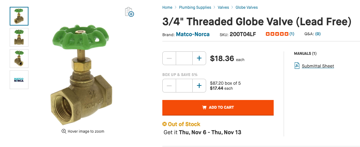
Use a balance or globe valve, with a wheeled handle so you can make fine adjustments. A globe valve like this with a tapered plug would be accurate enough for this job.
 Bob "hot rod" Rohr
trainer for Caleffi NA
Living the hydronic dream0 -
I had to google "outdoor reset" - no I do not have that. I see now you are using the globe valves as restrictions to force a portion of the water toward the radiant loop. This seems like the simplest approach and a brilliant use of simple, reliable adjustment valve.
If I have issues with water flow through radiant section I can add a second pump after mixing valve if needed w/o any real re-work in the future.
I am going to get this set up this weekend I'll follow up with my results.
Thank you!
0 -
There is a good chance that your current 20 year old boiler is over-sized. So keeping this all one zone will be the best way to run the system.
Balance valves are uncommon in residential work, but they serve a good purpose to maximize a system design or allow you to make adjustments further down the road if things change in the system.
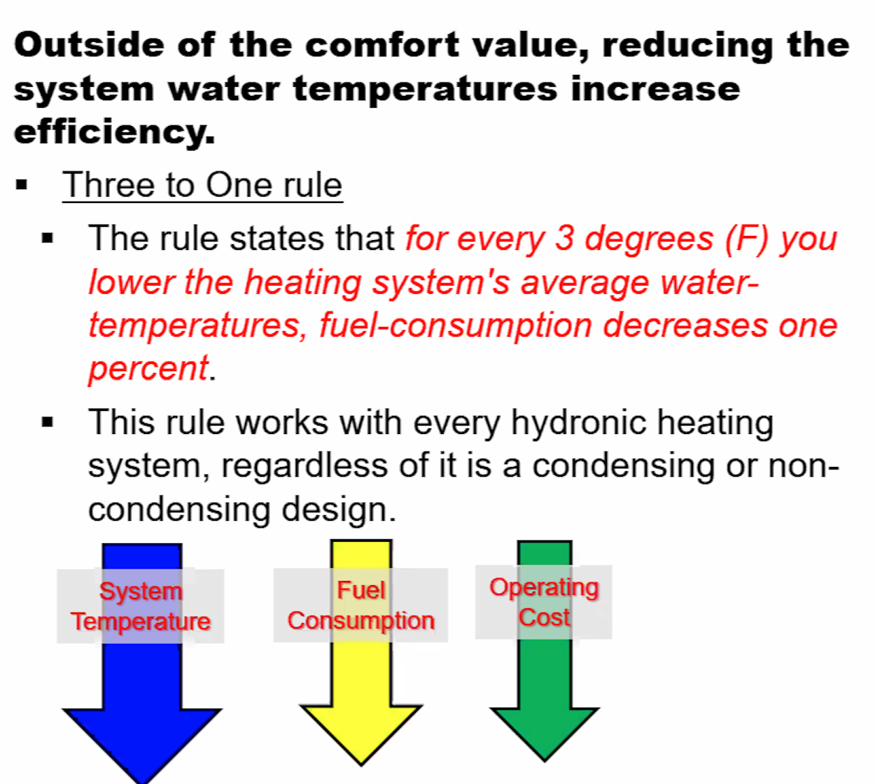
Adding an outdoor reset helps keep the boiler running more efficiently, helps prevent temperature over-shooting. It should reduce boiler cycling and save some fuel. Might be worth looking into someday.
 Bob "hot rod" Rohr
trainer for Caleffi NA
Living the hydronic dream0 -
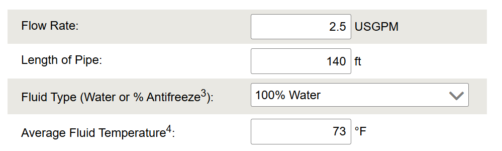
The PPI Plastic Pipe Design Calculator shows a head loss of 30 ft, for 2.5 GPM of 73F water through 1/2 PEX. Not a good design choice. You can check your values at Plastic Pipe Design Calculator.
 0
0 -
I wish I could go back and use 1" pipe but now it is permanently part of the construction. I can see where it is hurting me now that I have the system set up and bled. When I bleed the 3 other loops I get a great flow of water (at 30 psi not normal 20 psi operating pressure) out the hose for each loop. Until I get to the loop that has the radiant section that flow is substantially lower.
I am set up closely as detailed above the last sketch by Hot Rod. My house system is not impacted and that seems to be working normally using my contactless thermometer. I have the globe valve in the radiant section wide open and no restriction in the other lines. I did not add globe valve to the radiator circuits that is going to be a major task. I do however have a ball valve in each circuit before it returns to the main trunk back to the boiler.
Currently I am getting essentially no real heat into the radiant section. As that run of copper gets closer to the mixing valve it is generally warm versus outright hot for the radiator loops. Is this because I am not gettin a lot of water flow through the radiant loop? I have radiators downstream of the radiant loop they seem to be operating at normal temperature. I wonder if my mixing valve is being forced open and the water is bypassing the radiant loop? The pex is warm but not hot which I was expecting.
I'll take a series of temp measurements tonight when it is running to map it out better. I did see a 3 degree difference in floor versus the room next to it but not enough to be significant.
0 -
You need to choke down the radiator loops to force flow through the smaller, higher pressure drop radiant loop(s)
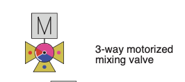
If you are not using a pump downstream of a thermostatic, you will not get much flow. My post above indicated a manual 3 way valve instead. I should have labeled the icons better.
Here is an example of a 3 way thermostatic symbol compared to a 3 way motorized. Remove the square M and you have a manual 3 way valve symbol.


A work around is take the top off the 3 way thermostatic and pull the guts out. Now you have a 3 way fitting, a tee :) I think you will now be able to balance.
The ball valves at the radiator returns at your manifold can be used as balance valves. Not much flow balance happens as you first start closing a ball valve. You adjustment range will be 50% closed and on.
After 50% and above a ball valve gets a bit finicky to adjust flow. A tiny movement is what it takes. I generally just tap the handle to get that fine resolution
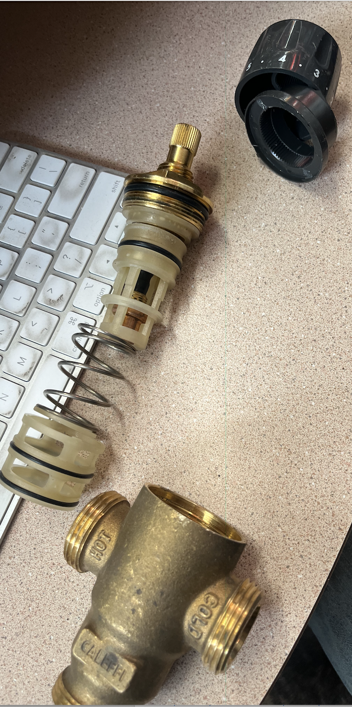
For the 3 way thermostatic work around, remove the phillips screw from the valve handle. Pull the knob and ring below off. Should be a large square or hex. Unscrew that and here is what you find. Depending on the brand and model of valve? There will be some spring tension when uyou unscrew the top nut, so be prepared and not to lose the parts as they eject.
Take a pic of the pieces like this in case you ever want to reassemble.
Now put the very top brass part back on. It is basically an expensive tee now, and with valves on the outlet you vary the flow, and mix temperature
Back in the olden days we built mix station with two ball valves as shown in the top pic here, As 3 way valves became more available we moved to those, either manual, thermostatic or motorized.
This shows the mix loop off a primary secondary so 2 pumps are required. I think your parallel piping, one pump, will work once you massage it a bit.
Bob "hot rod" Rohr
trainer for Caleffi NA
Living the hydronic dream0 -
I'll find an exploded view of my thermostatic valve hopefully I can disassemble it. Draining the system and re-bleeding - I can do it in my sleep now! I did discover I have a radiator down stream of the radiant loop and monitored the temp. As expected the temp before and after is the same since I am not shedding any heat to the radiant loop. When this is working I suspect that downstream radiator will be cooler and I may need to reconsider the loop layout but let's get the laundry room hot first!
Thanks
0 -
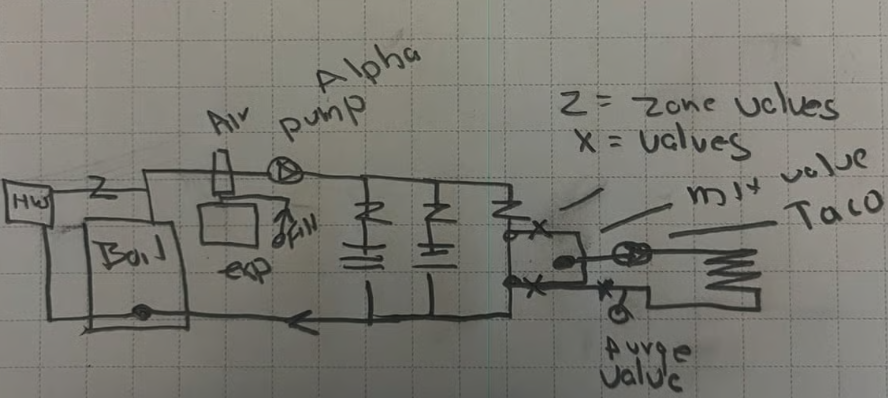
Thanks for staying with me! I pulled the inner valve out of thermostatic mixing valve making it a T. First item I noticed is the water flow back to the hose bib for bleeding the air out is much closer to the other loops. I also have a T in the radiant micro zone I use to bleed air out and water flow appears ok. I could probably measure it in gallons/hour using a bucket.
I have each of the loop return valves 50-60% closed and the globe valve on the radiant loop 2 1/2 turns out of 5 closed. It has not been very cold here yet but using my digital contactless thermometer I am not transferring vert much heat to the floor. It is not warm to the touch but is about 3 degrees warmer than the floor in the adjacent room.
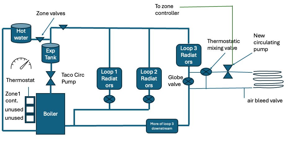
Updated drawing of set up
There is actually a 4th loop and a few small details I have discovered but this is the key points.
If I still have issues with insufficient heat should I add a 3 way valve and force the water into the radiant loop or should I add a second pump? If adding a pump I could use some help with specifications. I could tie it to the current controller or even just run it all the time in season.Thank you for any advice.
0 -
I had a similar project with my hydronic heat system when I added radiant floor loops on a zone in place of the former baseboard fin tube. With the helpful posts and troubleshooting of Hot Rod and others on here, I ended up re-plumbing the system to pump away on each zone. You could look up that whole thread if you think it could help.
1 -
I made an adjustment to my plumbing in an effort to force more heat into the space. My working theory was that the head pressure is directing water down the easier path and not very much into radiant section. I also updated my diagram with the oil fired hot water heater.
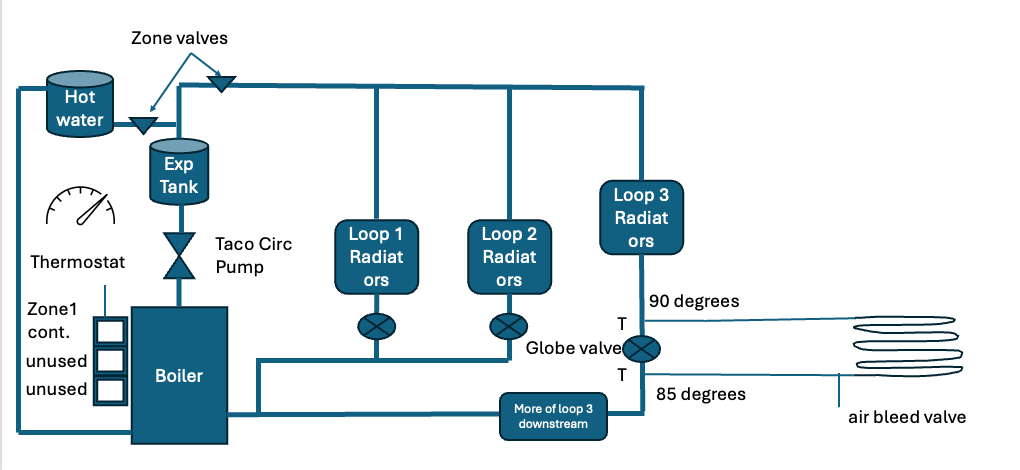
I removed the mixing valve and replaced with T and moved the globe valve to between the Ts. I was just not getting heated water into the loop based on holding the pipes with my hand. Now I can close this valve and force all water in this loop into the radiant section which is how I am running it now. I can confirm hot water is now circulating in the loop because the return leg is now at least warm versus cold. When the heat is running and I using a non-contact thermometer I see a 5 degree temperature drop between the end of the run before the T and when it returns. However my floor is still dead cold. My worry at the start of this project was over heating the floor so that is ironic!
I think this is because the floor is thick and the radiant loop is not hot very long. Maybe the burner runs 5 minutes or so to bump the temperature back up. The floor is 1 1/4 thick plywood, uncoupling membrane, thinset and then tile. In the few minutes the hot water is circulating and even sitting in the pipes after burner shuts off is not enough to transfer much heat. Just a guess but I am running hot water into the space and not moving the temp and there is a lot of pipe, transfer plates and insulation in there.
Any suggestions on how to solve this? Maybe run a circ pump in the radiant loop that keeps the water from the overall hydronic system moving? Pretty upset since it is getting into the 40s at night here and I have a huge amount of work in this project with no heat. Any way to leverage to hot water loop?
0 -
As you recall from the start most agreed a second circulator with a mixing device is the best, and surefire way to make this work closer to your expectations.
The radiant zone could be a bit constipated, not enough heat emitter surface area to transfer what the room requires. Knowing the heat load for just that space, and calculation what your actual un-encumbered floor space can actually transfer, will answer that question.
There is a bit of a mismatch between a radiant low mass floor and a cast radiator as far as heat profile,
One issue that pops up with a small radiant zone is it can cause short cycling of a fixed, non modulating boiler. AKA a micro-zone.
Sooo your original idea of one thermostat for the entire system has value if you take the time to tweak the flows. But the mass mis-match will still be a bit of a challenge.
Bob "hot rod" Rohr
trainer for Caleffi NA
Living the hydronic dream0 -
Thanks I had been considering the mass problem. It is not a block of concrete but it is thicker than subfloor and tile. I have a warm area in the room where the loop starts so it is all functioning it is just not going to keep the space warm (or even close). What is ironic is my first house had radiant first floor (slab) and fin second floor and it was one giant circuit the floors were hot hot! I was worried about that here but I cant get them even warm.
Some questions:
- Should I pickup the hot water for this new loop closer to the boiler not after the water has run through a few radiators and lost heat? Hotter water should increase the heat going into the mass.
- How do I size a pump for this application? Assuming around 120' of pex, water at 120 degrees at 2 gpm (is that a valid flow rate?).
- What if I run the radiant circulator constantly (in season)? Just keep circulating the water in the overall system?
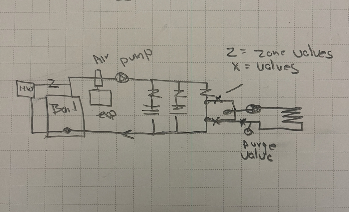
Two possible configurations
This my current set up with a circulating pump added. Switching on and off with house t-stat will help force more water into loop. Running it constantly would add more heat to the mass but I think it would be the same size pump.
Essentially the same set up but I am adding a branch off the main trunk to feed radiant section hot water before it passes through any radiators. Should be hot like 160 degrees. Then returning via main return trunk after going into radiator down stream. Pump controlled by t-stat/zone controller.
Thoughts on doing this w/ least amount of rework? Can I install pump as shown in first diagram and try it while tweaking valves and possibly running pump constantly? If that does not work and I go to option 2 I would be adding ~20' of 3/4" pex plumbing can I use the same pump? Because of the insulating nature of pex it is hard to compare temperature but I am going to measure the copper with the system running right before it enters pex to see the temp I am working with. I think it is cooled from radiators and I was hoping to prevent super hot floors.
Thanks HotRod for all your advice and time. Hopefully on of these will work but I could use some help on pump sizing.
0 -
typically you see around 80-82 degree surface temperatures for hard surface radiant floors.
The water temperature you need to awuire that depends in the r value of the floor build up. Wood, backer, tile maybe in your case. So a WAG 100- 120 supply temperature. With a 3 way thermostatic you have adjustability
82 degree surface in a 70 degree room gives you around 24 btu per sq ft output
For a single 120’ loop the smallest circ in low speed should do it.
Many brands to choose from. I like the Grundfos Alpha series the 15-58 size
Bob "hot rod" Rohr
trainer for Caleffi NA
Living the hydronic dream0 -
Thanks for the pump recommendation. I'll update my plumbing w/ the thermostatic valve, pump and globe valve I think this is the correct configuration. I am not 100% sure if the globe valve should be between the Ts to radiant section or after. I'll wire it with the current circ pump circuit and see how it performs.
 0
0 -
like this
Pump goes after, downstream of the expansion tank
Add ball valves at three way mixer for service, if needed
Purge valve at radiant return
A relay box for 4 or 5 zone. Its nice to have a spare
So for radiant to tun by itself, the boiler pump will start, zone valve opens and radiant pump starts
I think A Caleffi ZCV relay box can do those 3 functions for the radiant, let me check
If you buy an Alpha 15-58 use it for the boiler pump, it will modulate as zone valves open and close. Use the Taco you have for the radiant. You just need a basic single speed circ there.
 Bob "hot rod" Rohr
trainer for Caleffi NA
Living the hydronic dream0 -
Wow that would be a major re-fit of my heating system all the way back to the boiler. I have to keep this circuit separate and minimize impact on the house. When I add radiant in my kitchen I will need this level of refit.
What would be the benefit if I pick up my hot water closer to the main branch before any radiators to get the hottest water possible and use a pump to push it through the radiant loop and return it into the main return trunk? I could run this second circ pump on a t-stat in the space or on at all times to keep water moving into the loop even when boiler is off to heat the "mass"?
0 -
Without being in front of your system it is hard to kow how much work is involved. I don't see your drawing and mine being that much different, workwise?
I added a separate branch just for the radiant instead of piggybacking onto the radiator loops corrected the pump location and deleted the globe valve. If you want the radiant as a stand alone zone, you can't add it onto the end of a radiator loop.
It comes down to how much you want to bite off, I suppose.
 Bob "hot rod" Rohr
trainer for Caleffi NA
Living the hydronic dream0


Categories
- All Categories
- 87.7K THE MAIN WALL
- 3.3K A-C, Heat Pumps & Refrigeration
- 59 Biomass
- 430 Carbon Monoxide Awareness
- 129 Chimneys & Flues
- 2.2K Domestic Hot Water
- 5.9K Gas Heating
- 122 Geothermal
- 170 Indoor-Air Quality
- 3.8K Oil Heating
- 79 Pipe Deterioration
- 1.1K Plumbing
- 6.6K Radiant Heating
- 396 Solar
- 16K Strictly Steam
- 3.5K Thermostats and Controls
- 56 Water Quality
- 51 Industry Classes
- 51 Job Opportunities
- 17 Recall Announcements