Please Criticize My Boiler Install

Unit is Rheem Combi-boiler 199K. Heat side is feeding 10 hydronic radiators, and 2 towel warmer radiators. DHW is 2 full bath, kitchen sink, dishwasher, washing machine.
A couple notes:
1. The main heat manifold is not completely level. This is the 1" pipe that does into the pump. This was a mistake that was not realized until that manifold was complete. It is off by about 1/4" from left to right.
2. I missed a shutoff valve for the potable water expansion tank. It can be isolated between two other valves, so I elected not to add it. I can if it is a big deal.
3. Pump will run in delta-P mode prompted by the opening of mechanical thermostats at each radiator. It has internal backflow preventer.
4. When we set the fill valve to fast fill, the pressure release valve at the top of the boiler allowed water to flow through. The two other pressure release valves did not open. This is the reason the floor is wet.
5. The setup on the bottom of the boiler is, Left back, 1" heat supply; left front, 3/4" dwh supply; right back, heat return; right front, dwh inlet.
6. Between my helper and me, we got about a dozen metal splinters doing this. The propress tool seems to create metal splinters. Ouch!
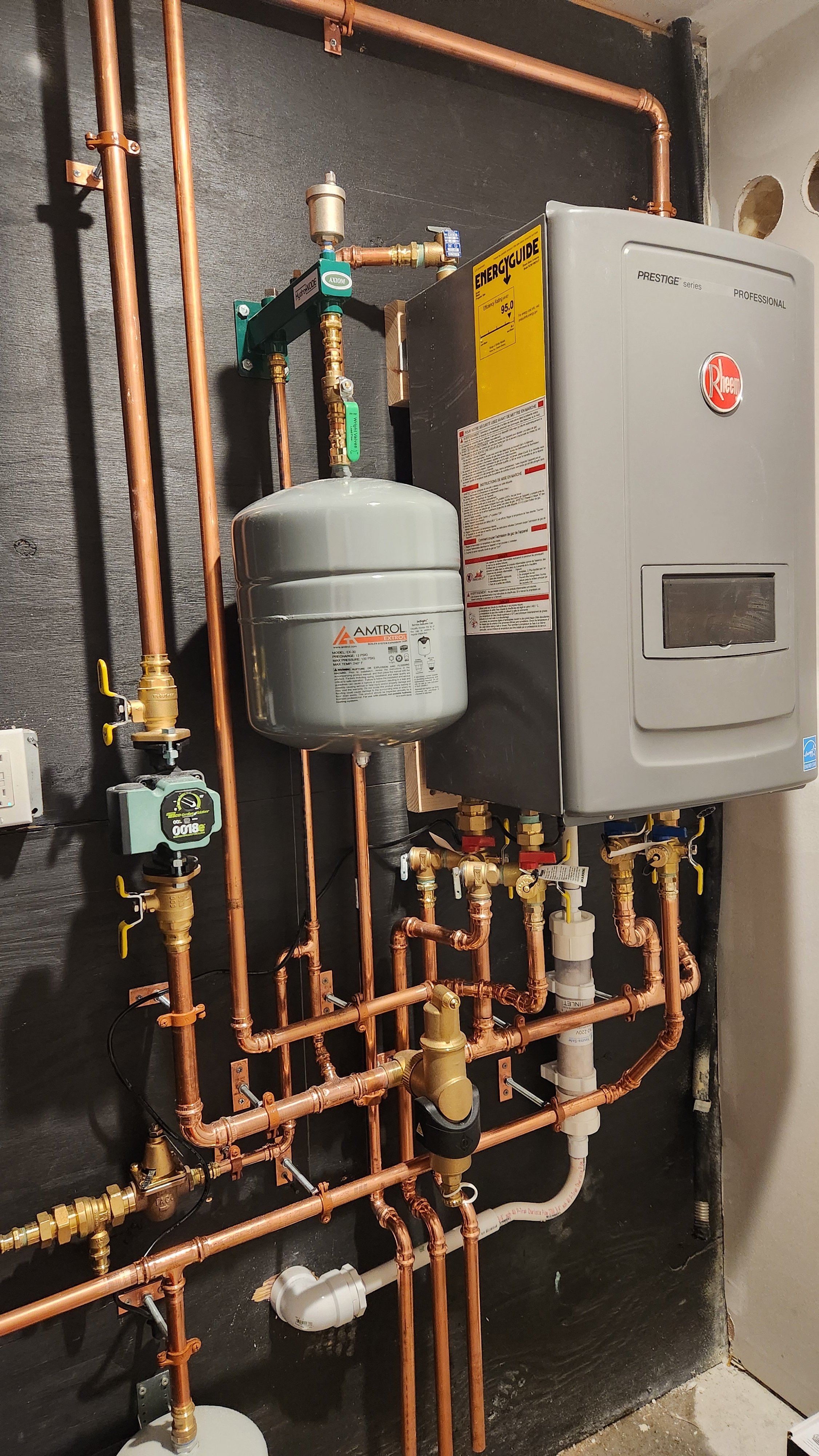
I have more pictures if something is out of view. Looking for a critique of this setup and the quality of work. Thank you for looking at this. This forum has really helped a lot.
Comments
-
The piping looks great, but if you've got 12 different mechanical stats, this boiler is going to have a huge short cycling problem on warmer days when only a couple are calling for heat. Also, your closely spaced tees are not closely spaced so hydraulic separation is minimal at best.0
-
Looks pretty good. How is it performing?0
-
Looks good.
I don't care for propress being close coupled but I guess that's just me, that's the way propress is. If you have to repair something you waste out a lot of fittings1 -
I agree , I don't like tight piping . But the job looks cool . Varnish the pipe so they don't turn ...
There was an error rendering this rich post.
1 -
Looks fine. Is the backflow vent port piped behind the wall?
Maybe add a thermal expansion tank, these are commonly used on tankless and combis. Different colors available")
With that many zones, see what function the control has to lessen cycling.
Anti cycling allows you to set a time interval between firing
Step firing or ramp delay would allow you to stay on lowest fire for a time period.
And limit the max. firing rate to match the heat load at design.
Close tees are a bit wide, but I doubt it will induce flow in the distribution loop, especially if there is a check in the main circ and zone valves.
;Bob "hot rod" Rohr
trainer for Caleffi NA
Living the hydronic dream 1
1 -
100% Agree!EBEBRATT-Ed said:Looks good.
I don't care for propress being close coupled but I guess that's just me, that's the way propress is. If you have to repair something you waste out a lot of fittings0 -
Regarding the short cycling, the way we set up the first unit, the circulator runs independently from the boiler. As long as a mechanical thermostat is open, the circulator is running and moving water through those open loops.
Each radiator is on its own loop and can call for heat independently. The boiler runs delta T, so when the water drops to a certain temp, the boiler fires and brings it up to the high point. I think the first one was something like 130-160. That prevents the short cycling. As long as the water in the system is over 130, it circulates without boiler firing.
The first one is working great. When it is cold out, the circulator runs about 50% of the time (at varying speeds) as each of the 12 zones call for heat when they need it. All the radiators are always a little warm, and sometimes very warm when they are calling for more heat. The boiler fires intermittently for a few minutes at a time when the temp drops. The new owners love it.
Thanks for all the feedback.0 -
1. Can you explain the backflow vent port? The fill valve has a backflow with a vent. You can see it just above and behind the potable water expansion tank at the bottom. Is that what you mean?hot_rod said:Looks fine. Is the backflow vent port piped behind the wall?
Close tees are a bit wide, but I doubt it will induce flow in the distribution loop, especially if there is a check in the main circ and zone valves.
;
2. No zone valves. The supply runs to a 12 port valved manifold. Each of those ports run to a hydronic radiator with a mechanical thermostat that opens the internal valve when the temp drops.
The return comes back to a 12 port manifold than goes into the return you see on the right of the boiler. the circulator has a built in check valve. I wondered if we should use more, but we did not with the first build. It is something I could add, though, if you think it will be a problem without.0 -
Not too bad..gotgas said:This is my first solo install. Not a licensed plumber or HVAC tech. The whole thing is going to be gone over by my plumber when he gets over. All gas work being done by licensed propane company.
Unit is Rheem Combi-boiler 199K. Heat side is feeding 10 hydronic radiators, and 2 towel warmer radiators. DHW is 2 full bath, kitchen sink, dishwasher, washing machine.
A couple notes:
1. The main heat manifold is not completely level. This is the 1" pipe that does into the pump. This was a mistake that was not realized until that manifold was complete. It is off by about 1/4" from left to right.
2. I missed a shutoff valve for the potable water expansion tank. It can be isolated between two other valves, so I elected not to add it. I can if it is a big deal.
3. Pump will run in delta-P mode prompted by the opening of mechanical thermostats at each radiator. It has internal backflow preventer.
4. When we set the fill valve to fast fill, the pressure release valve at the top of the boiler allowed water to flow through. The two other pressure release valves did not open. This is the reason the floor is wet.
5. The setup on the bottom of the boiler is, Left back, 1" heat supply; left front, 3/4" dwh supply; right back, heat return; right front, dwh inlet.
6. Between my helper and me, we got about a dozen metal splinters doing this. The propress tool seems to create metal splinters. Ouch!
I have more pictures if something is out of view. Looking for a critique of this setup and the quality of work. Thank you for looking at this. This forum has really helped a lot.
Personally i would have done the following another way :
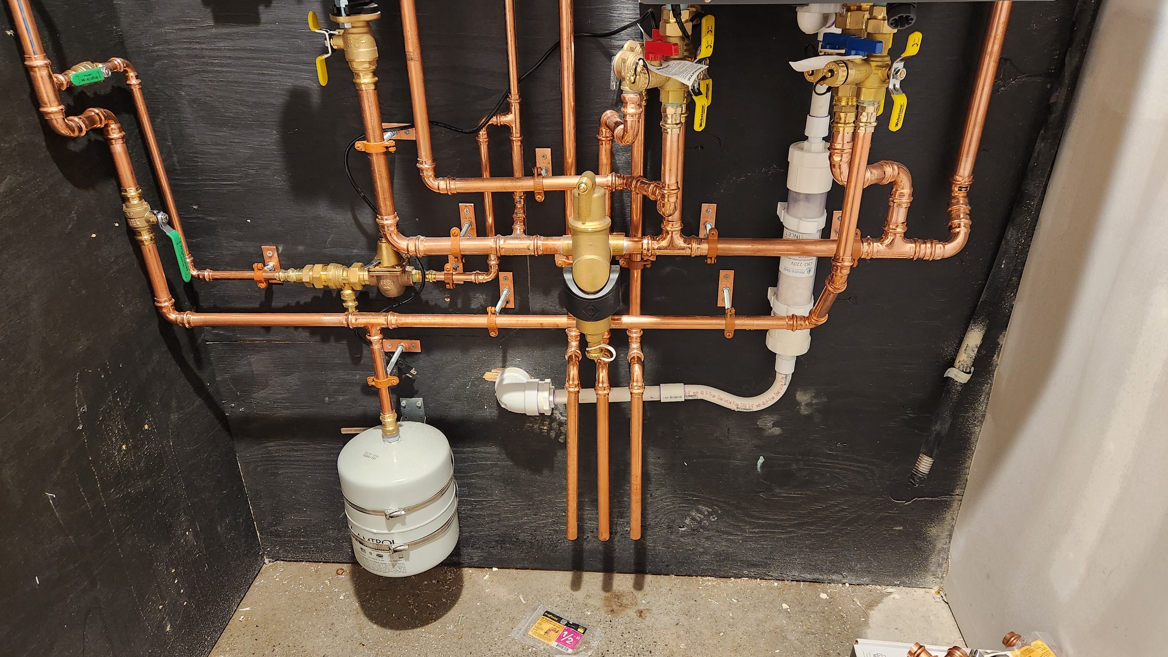
1. The closely spaced tees should be closer.
2. The heating system exp. tank should have a "Service" drain after the shutoff have.Webstone makes a nice one...Or..."Next Time" Axiom makes the Hydronde with it.
3. Any relief equipment should have a union for future service..We use MIP sharkbites which will allow the service person to unthread it without having to cut the pipe and recouple it.
4. The electrical line needs more support as per code.
5. The backflow preventor has not relief piping as per Code.
6. We like to install a shutoff between the Fill/BFP Combo and the system so that it can be serviced without draining the heating system.
7. We like to install a Union between the Fill/BFP Combo and the shutoff valve so that the unit can be service better.
8. We install our condensate neutralizers horizontally for a better contact time.
9. We install our condensate Neutralizers with unions so they can serviced.
10. We Never direct pipe our Neutralizers to the boiler (Air gap needed).
11. Our Code official will not pass a system that does not have a bypass on the Neutralizer.
12. We like to use unistrud vs studs and clamps.
13. Venting and combustion air ?
14. Outdoor sensor ?
15. Any penetrations should be sealed with elastometric cauking as per our code.
BTW...After you press the joint, do not remove the press tool until you rotate the the head back and forth a couple times...This will remove the sharp burr that can cut you. you can also use a file or a grinding tool to remove the burr.")
Have fun balancing your TRV system. 1 -
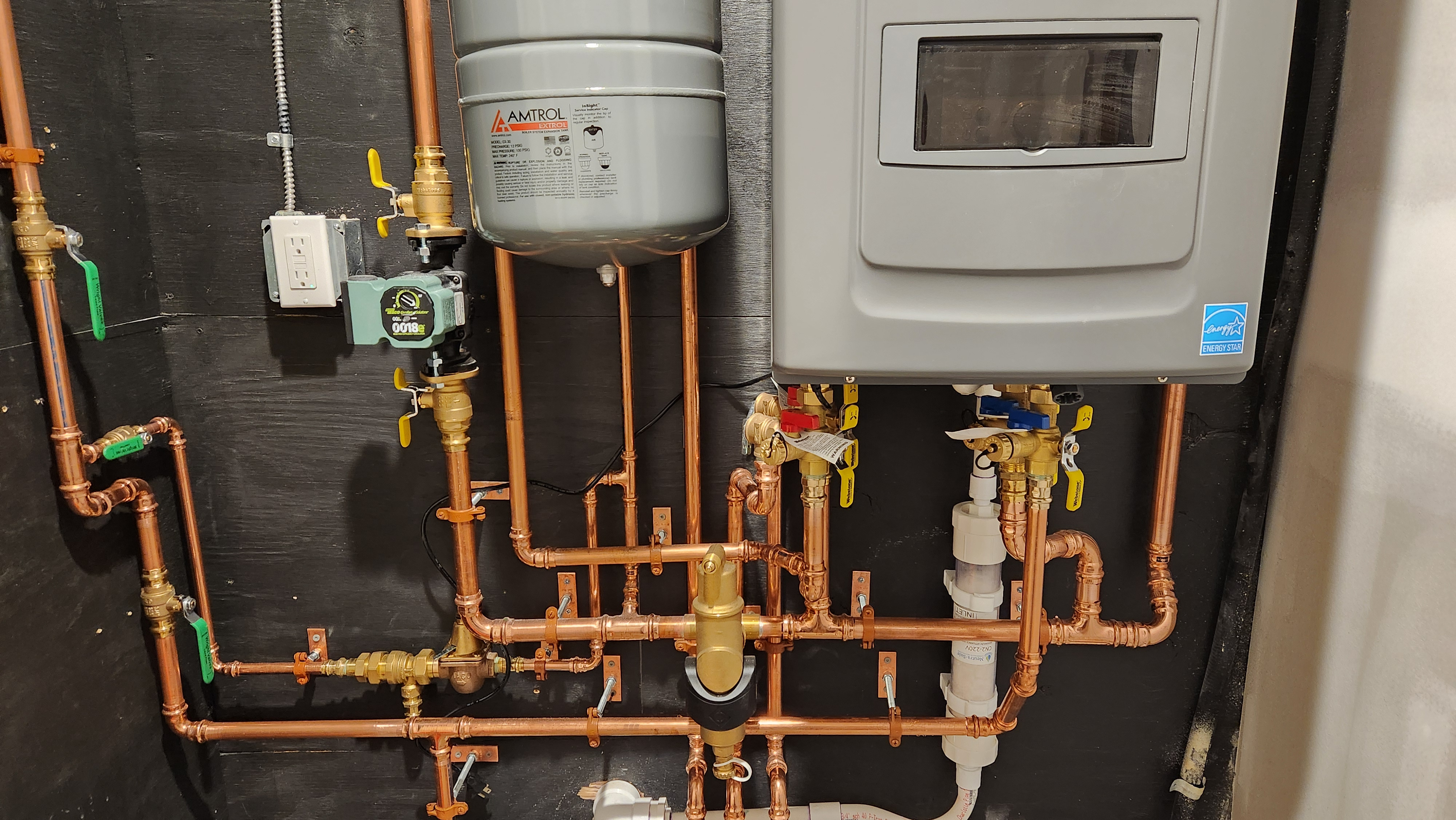
The "closely spaced T's" being referred to are the large 1" (or 1 1/4") that are coming out of the boiler's main supply and return ports (w/ red and blue shut-off valves). Yours have been installed slightly farther apart than "closely". Look up the term "hydraulic separation."1
-
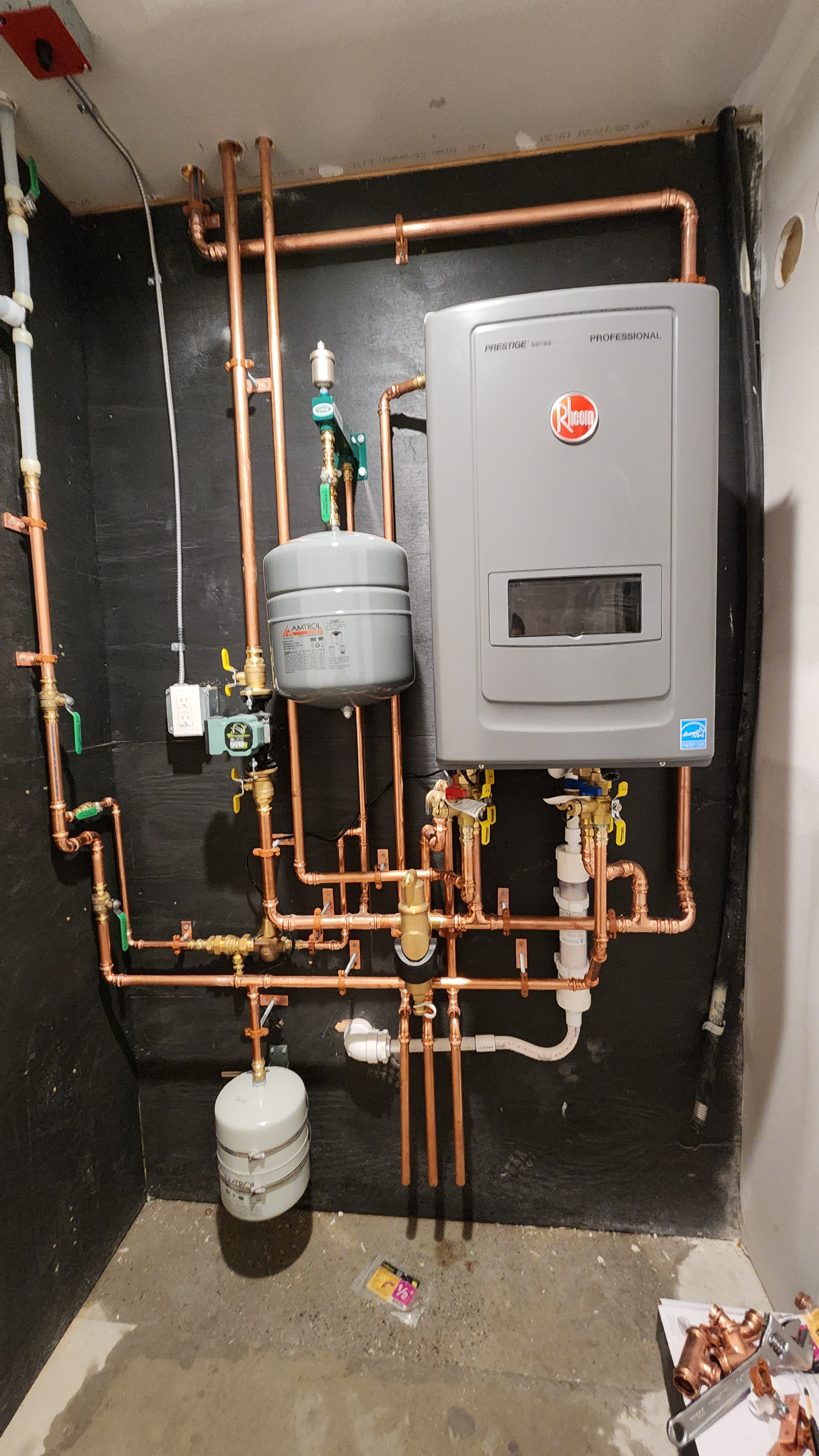
I may have missed it, but I don't see an emergency shutoff switch in the photos. I may be wrong, but I think that is a heat sensor of some sort on the ceiling?0
-
Thank you. This is a lot of info.Derheatmeister said:
Not too bad..
Personally i would have done the following another way :
1. The closely spaced tees should be closer.
2. The heating system exp. tank should have a "Service" drain after the shutoff have.Webstone makes a nice one...Or..."Next Time" Axiom makes the Hydronde with it.
3. Any relief equipment should have a union for future service..We use MIP sharkbites which will allow the service person to unthread it without having to cut the pipe and recouple it.
4. The electrical line needs more support as per code.
5. The backflow preventor has not relief piping as per Code.
6. We like to install a shutoff between the Fill/BFP Combo and the system so that it can be serviced without draining the heating system.
7. We like to install a Union between the Fill/BFP Combo and the shutoff valve so that the unit can be service better.
8. We install our condensate neutralizers horizontally for a better contact time.
9. We install our condensate Neutralizers with unions so they can serviced.
10. We Never direct pipe our Neutralizers to the boiler (Air gap needed).
11. Our Code official will not pass a system that does not have a bypass on the Neutralizer.
12. We like to use unistrud vs studs and clamps.
13. Venting and combustion air ?
14. Outdoor sensor ?
15. Any penetrations should be sealed with elastometric cauking as per our code.
BTW...After you press the joint, do not remove the press tool until you rotate the the head back and forth a couple times...This will remove the sharp burr that can cut you. you can also use a file or a grinding tool to remove the burr.
Have fun balancing your TRV system.
1. Do you think this is a critical problem? This first one we did was about 3" closer. Is this something we need to go in and change?
2. I understand. We are going to do that.
3. Good thought.
4. That is just laying there. It is not installed yet.
5. We will add this.
6. We will add this as well.
7. Great idea. This going in the "Do it next time file."
8. This is marked for either vertical or horizontal. Do they not work as well vertical?
9. The ends of the neutralizer is threaded and can be unscrewed and the cartridge pulled out. Is that sufficient?
10. We missed that and will correct.
11. I will have our guy look at this before it is inspected.
12. Can you point me to this product?
13. Coming soon.
14. Being installed by propane company.
15. Being done soon.
Good tip on the burrs. I got a large metal splinter right into the middle of my thumb pad. That hurt, and now my phone is not recognizing my fingerprint unlock.
Thanks for all the thought and time you put into this.0 -
It is right outside the door to the left in the pictures. The ceiling box is a heat sensor. Our code officer wanted the shutoff outside the door.ScottSecor said:I may have missed it, but I don't see an emergency shutoff switch in the photos. I may be wrong, but I think that is a heat sensor of some sort on the ceiling?
0 -
Regarding the closely spaced tees, several people have commented on this. If this something we need to alter? Does it matter as much because we only have one circulator on the system?psb75 said:The "closely spaced T's" being referred to are the large 1" (or 1 1/4") that are coming out of the boiler's main supply and return ports (w/ red and blue shut-off valves). Yours have been installed slightly farther apart than "closely". Look up the term "hydraulic separation."
0 -
Only one circulator? The boiler doesn't have one built into it? The entire purpose of the closely spaced tees is to provide hydraulic separation between the circulator for the boiler and the circulator for heating zones. Mixing occurs between the tees.
I'm not familiar with that boiler. I'd make sure to check if it has a boiler circulator built in to it.0 -
Yes the boiler has a built in circ, its a combi.
It's hard to say exactly what if any issues you may encounter from the lack of flow separation. If the external circ is running while the diverting valve is moving positions it may stick, or not move position correctly, the heat exchanger may get incorrect flow which could cause issues depending on how exactly the boilers internal logic work.
4 times the pipe diameter maximum distance between the tees, with 6" of straight pipe on either side.
0 -
Yes, you are correct. The boiler also has a circ.SuperTech said:Only one circulator? The boiler doesn't have one built into it? The entire purpose of the closely spaced tees is to provide hydraulic separation between the circulator for the boiler and the circulator for heating zones. Mixing occurs between the tees.
I'm not familiar with that boiler. I'd make sure to check if it has a boiler circulator built in to it.
What is the verdict here? The tees are about 8" apart. This is a 1" pipe. Am I looking for trouble if I do not cut that down to 4"?0 -
Looks very nice. I did not read all the comments. That Boiler has two relief valves? Everybody’s a stickler and one fashion or another. My claim to fame is trying to minimize the 90s as much as possible. As in no more than necessary. But very nice job.1
-
What system are you using to integrate the TRV into boiler call for heat? Is this install in US or Europe?0
-
It's the flow resistance between the two tees that could allow some flow to the distribution loop.
If you knew the flow rate through the boiler and that section of pipe you could do some calculation as to what that pressure drop is.
Even IF some flow was induced with a check in the Taco system pump it would prevent unwanted flow.
A book called Primary Secondary Pumping Made Easy is states
"As a rule the shorter the common piping the better. Ideally the common piping should not be more than two feet long, (but it can be as short as a close nipple)
It can be longer than two feet but you'll begin to have hot water straying into places where it shouldn't be."
Dan Holohan September 2000
I would not change any piping in your system, it will work just fine as piped.Bob "hot rod" Rohr
trainer for Caleffi NA
Living the hydronic dream2 -
The TRVs are Pensotti A40400A. When they open they allow the circ to push water through the radiator loop. The circ is running in delta p mode so it ramps up to meet the demand if many zones are calling for heat, or runs lower if it is only one zone. If none are open it idles.PC7060 said:What system are you using to integrate the TRV into boiler call for heat? Is this install in US or Europe?
The boiler is checking temps on the circulating water and when it drops below the low limit, the boiler kicks on and heats the water in the loop. There is no communication between the boiler and the TRV, only response to temp.
This is in the US, but according to Pensotti it is a standard European setup. We ran our plans by them and they loved it. They said they want people to do this but it is not widely accepted. 1
1 -
I almost bought that book when I was doing this. I will buy it if I do another. Thanks for the encouragement on this. I appreciate all the help.hot_rod said:
A book called Primary Secondary Pumping Made Easy is states
"As a rule the shorter the common piping the better. Ideally the common piping should not be more than two feet long, (but it can be as short as a close nipple)
It can be longer than two feet but you'll begin to have hot water straying into places where it shouldn't be."
Dan Holohan September 2000
I would not change any piping in your system, it will work just fine as piped.0 -
-
It might be handy to have a second shut-off switch near the boiler. Just wire them in serie.gotgas said:
It is right outside the door to the left in the pictures. [...] Our code officer wanted the shutoff outside the door.ScottSecor said:I may have missed it, but I don't see an emergency shutoff switch in the photos. [...]
1 -
Don't you need a siphon on the condensate evacuation to avoid sewage odors?0
-
This is the proper vertical installation, yes this is for your Neutra-safe unit. It's in the instructions.

1 -
I'm not sure I like the wall colour!!! Black is so dark and depressing. Next time maybe you can get something more vibrant like persimmon or tangerine.Said no boiler man ever!
LOLEdward Young Retired
After you make that expensive repair and you still have the same problem, What will you check next?


 4
4 -
Where does the condensate pipe go after it disappears in to the wall?0
-
That little bent pipe is supposedly a trap. I am not a fan. Does a pro ever use this?The trap is usually in the boiler, but a second one is not the end of the world.
Good call @dko on the neutralizer piping. The "Optional atmospheric vent...." on the left is important. If the condensate drain ever clogs, you don't want it backing up into the boiler's heat exchanger.8.33 lbs./gal. x 60 min./hr. x 20°ΔT = 10,000 BTU's/hour
Two btu per sq ft for degree difference for a slab0 -
for a condensate pan on an air handler to keep it from pulling air in or out of the plenum through the condensate pipe.gotgas said:
That little bent pipe is supposedly a trap. I am not a fan. Does a pro ever use this?Sylvain said:Don't you need a siphon on the condensate evacuation to avoid sewage odors?
you should really have a full size trap and a standpipe and possibly a real or mechanical vent depending on how it connects to the drainage system0 -
you should really have a full size trap and a standpipe and possibly a real or mechanical vent depending on how it connects to the drainage systemDo we even know that it drains into the sanitary system?8.33 lbs./gal. x 60 min./hr. x 20°ΔT = 10,000 BTU's/hour
Two btu per sq ft for degree difference for a slab0 -
Right- plumbing code is a different animal. If that’s a plumbing system he tied into, not good (Massachusetts plumber here)Do we even know that it goes into the sanitary system?0 -
Had to be away for a little while. That condensate does go into the sanitary system which ties into city sewer. What is the danger for this? Codes enforcement did not seem to care, but I do not want the home buyer to get shafted in the future because we did it wrong.
We are adding a couple more valves as detailed above. One big oversight that is not visible is the manifolds are in the attic accessible, but not convenient. We should have installed a purge/flush on the return coming down on the right side of the boiler for bleeding the air from the whole system.
There are 4 loops in the system that go to radiators on the other side of a 14' vault, so those are long loops. It took forever to work all the air out of the system, even bleeding at the radiators. We kept getting "low flow" shutdowns because so much are was coming back in the returns. It is fine now, but it would have been nice to capture that air before it got back to the boiler.
Lesson learned on that.
0 -
Ideally, the condensate drains outside into dirt. Use a condensate pump to lift it if it's below grade.
If you can't get it outside and need to drain into the sanitary system, code says - at least in my area - you need a trap, indirect waste and vent. A pain in the tokus and if this is your lowest fixture and if the drain clogs further down the line, you will have a flooded boiler room and won't know about it until it starts smelling upstairs unless you put a backflow preventer on the drain.
If you plan ahead, you can also drain it into a branch tailpiece on a bathroom basin or kitchen sink if nearby.
8.33 lbs./gal. x 60 min./hr. x 20°ΔT = 10,000 BTU's/hour
Two btu per sq ft for degree difference for a slab2 -
or dump it into them foundation sump / drain tile if available.
1


Categories
- All Categories
- 87.7K THE MAIN WALL
- 3.3K A-C, Heat Pumps & Refrigeration
- 59 Biomass
- 430 Carbon Monoxide Awareness
- 127 Chimneys & Flues
- 2.2K Domestic Hot Water
- 5.9K Gas Heating
- 121 Geothermal
- 170 Indoor-Air Quality
- 3.8K Oil Heating
- 79 Pipe Deterioration
- 1K Plumbing
- 6.6K Radiant Heating
- 396 Solar
- 16K Strictly Steam
- 3.5K Thermostats and Controls
- 56 Water Quality
- 51 Industry Classes
- 51 Job Opportunities
- 17 Recall Announcements