PLC cold water "Rejection" mixer? (revised)

In re-thinking this project, I now realize that the "twin" Rinnai CU199iN DUO Hybrids are short of their peak cold weather load demand.
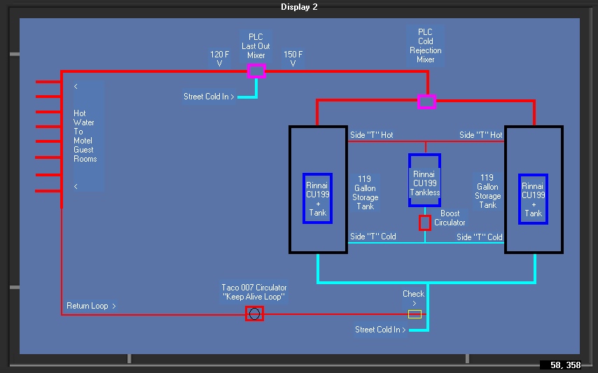
Tank storage volume is fine, but need to recover faster. So, I plan to add a third CU199iN "Tankless" to the mix in the following fashion (see attached pic).
Adding this third tankless in the center of the "balanced" "T" piping preserves the Rinnai requirement for equal work flow thru the storage tanks.
Rinnai support says this can't be done because of the programming for this "Twin" DUO Hybrid configuration.
I don't see why this added "balanced" pipe and additional middle CU199 unit would not work as shown.
........ any thoughts on this?
Comments
-
Two V075C2D2ZA024Q4A2 potable water 10.3CV 3/4 ball zone valves at inlet T of extra CU199 will direct flow to the down tank. $310 each0
-
Hi Teemok!Teemok said:Two V075C2D2ZA024Q4A2 potable water 10.3CV 3/4 ball zone valves at inlet T of extra CU199 will direct flow to the down tank. $310 each
I don't feel I now need to separately design a "steering" (zone valves) solution to address the fault condition of failed heat loss in the storage tank.
Correct me if i'm wrong, but I feel this revised and expanded design, as is, in of itself "self heals" from the failing downed tank instantly (recovery started) and without letting the 119 gallons of water go cold ... all without human intervention as well as to serve as the needed BTU booster!
0 -
Flow traffic jam at the tank ports if connected where existing CU199 connects. What are those pumps flowing? 9-11 GPM each? Got to watch velocities. Are there auxiliary ports on the tanks? I guess you could pull from cold and supply to hot outlet. Still might be a flow traffic jam with high DHW demand flow. If the extra unit can't get cold water to it, it won't put out the BTU's. Two pumps running in the same tank might stir the tanks too much, mixing up any stratification there might be. I thought fault back up was the goal, now you're doing added recovery.0
-
Flow traffic jam at the tank ports
How so? ......the primary flow is out the top of the tank.
please elaborate.
What are those pumps flowing? 9-11 GPM each?
PLC variable speed/flow controlled circulators
If the extra unit can't get cold water to it, it won't put out the BTU's.
Why would it not receive cold water? all the CU199 units receive their supply from the same balanced input piping.
Two pumps running in the same tank might stir the tanks too much, mixing up any stratification there might be
Tha PLC controlled circulators,mixers, etc allow me to turn on/off, speed up/speed down, etc. to address these issues any time its needed.
I thought fault back up was the goal, now you're doing added recovery.
Yes! .... but now this resolves both with "AI" (coded logic) to gracefully manage the system crisis on its own.
Why would I want the faulty tank to just sit there over the weekend till the service guy shows up when I can circumvent the fault's ill effects (cold water) and immediately start recovery heating of the failed tank and enjoin the recovered tanks heat contribution back into the system..
0 -
...... the "rejection" mixer will not allow any cold water path (ie: the failed tank) to the hot supply out port.
There will be times the PLC will assign more priority to meet current load demand and service recovery efforts at a lower demand time of the failed tank.
Recovering a 119 gallon of "warm" water is a lot faster than trying to recover a 119 gallon of "stone cold" tank of water.0 -
I know this may not be helpful for your current predicament, but should you ever need to re-design this from the ground up, or for someone else, consider a couple of large indirect water heaters, that way you could use as many boilers as you want to heat the tanks and have multiple levels of redundancy, and no cold tanks unless every boiler was failed. This setup looks to be about as expensive but with more points of failure and the added concern that if a unit fails its tank goes cold (which is the issue you are aiming to fix) This whole setup kind of feels like taking a system and reconfiguring it for a purpose it doesn't really jive with, when the much simpler tried and true would be more efficient and more than likely around the same cost, at least after you consider the amount of changes being made to sort of a simulate a traditional system with tankless water heaters.

 2
2 -
I have not seen a Duo yet but the older models have 3/4 trappings at the tank. Lets see: The alpha is good for 30ft of head @ 6GPM (CU199 flow @30ft) that gives about a 65F rise. All three units running with perfect balanced flow means about 9GPM wants to travel through all the heating loop ports. Ball park 7ft/sec. Not so bad I guess.
As for the 3rd CU199 seeing cold: If your piping is balanced, half the flow would come from the low port of the hot tank mixing with the cold tank. The PLC starts restricting flow in the down tank at 120F outlet. I'm not pretending to accurately model what the 3rd CU199 would see but it won't be cold water.
If the 3rd CU199's set point is 185F and inlet is 115F mixed with hot tank's (XF temp) it sees what? It starts to modulate down when there's less than a 65F rise. So hot tank and cold tank return mix is above 130F most of the time. Peak BTU output of the 3rd CU199 would be at start up seeing (I'm guessing) a 55F rise and it quickly declines as the down tank recovers. It might also be shifting some BTU output from the tank mounted CU199 to the 3rd CU199. It may work, especially with AI") controlling. That's funny.
controlling. That's funny.
It would make more hot water and recover faster while providing a back up heat source for a failed tank unit. It's not a great solution for burner capacity utilization or efficiency. I'd rather see three tanks at low temperature or storage separate with Rinnai's in a linked bank.0 -
Meeting peak loads and planning for inevitable heating unit failures is typically handled with true redundancy. I maintained a system that adjusted tank storage temperature to meet peak loads but it had twin volume water heaters, where one was able to meet peak alone. Complex control schemes and programing and scabbed on heaters seems like mitigation of a design problem. Typical limits are gas volume, equipment room space and money. Prior investment is the worst.0
-
I hear ya Teemok! .... all good stuff ya got here!
yes! not an ideal setup ..... but as is most the time we have to work with what we got : (
I'll incorporate your good points here.
Thank you for your good analysis of this project!2 -
Current updated configuration (see attached pic)
I have eliminated the need for the "rejection" mixer function, as I now never let the failing tank to significantly loose its stored heat in the event its tank mounted heater failure.
The manufactures design of these "Twin" DUO units are such they are truly stand alone in operation and have NO communication between them.
If one failed ..... the other would NOT know about it. Eventually allowing the failed tank to contribute a steady 50% cold only water mix to the hot out feed. : (
In my current configuration, I am "physically" enjoining all three units by balance cross piping the internal side heating loops.
This creates a "double" loop, with only one circulator and the center water flow pipe in between the two tanks functioning as the heat exchanger between the two tanks.
Now , all three heating units work as one!
The center "Balancing" circulator running 24/7 continuously distributes the net produced heat evenly throughout the entire system ...... even in the event of a failed heat unit (in essence, I got the units to "talk to each other" physically) : )
0 -
...... This is the PLC controlling the digital mixing valve ..... min .25 to max. flow ..... all in one valve! (No "High/Low" units).

0 -
It would be more efficient to you have the 3rd until in standby until there's a temperature drop below a min in one of the tank outlets. PLC monitor of course. 3rd pump on a PLC relay. 3rd unit could be set at 185F and the others work as designed at 140F. The booster/backup kicks in when supply nears 120F in either tank.
Less wear on components and more efficient. Add two high temperature checks on 3rd unit supply T.
What model valve/s are you using at the PLC 120F mixer?0 -
I've been wondering this all along. If you build and program a DHW temperature device that fails and someone or many get burnt, who's on the hook? I'd let the corporations do the mixing and you limit your liability. If your heat source is solid and your recirc. piping is right, why incur the risk?0
-
Maybe a code approved 3rd party mixing valve installed after all of the owner built devices would suffice to protect against that? seems like a good idea either wayTeemok said:I've been wondering this all along. If you build and program a DHW temperature device that fails and someone or many get burnt, who's on the hook? I'd let the corporations do the mixing and you limit your liability. If your heat source is solid and your recirc. piping is right, why incur the risk?
definitely seems like a ton of liability to take on though doing it yourself, possibly not even legal if the valve doesn't have the appropriate code approvals0 -
Teemok said:
It would be more efficient to you have the 3rd until in standby until there's a temperature drop below a min in one of the tank outlets. PLC monitor of course. 3rd pump on a PLC relay. 3rd unit could be set at 185F and the others work as designed at 140F. The booster/backup kicks in when supply nears 120F in either tank.
Less wear on components and more efficient. Add two high temperature checks on 3rd unit supply T.
What model valve/s are you using at the PLC 120F mixer?
It would be more efficient to you have the 3rd until in standby until there's a temperature drop below a min in one of the tank outlets
I was thinking just the opposite! Think: we actually have three (3) storage tanks in this system. Two Rinnai 119 gallon storage tanks ..... and the third "equivalent" hot water storage tank (130 gallons) comprised of the totality of the hot supply and return pipe volumes. Lets call this our "virtual" hot water storage tank.
At Idle system flow, this "virtual" tank uses NO hot water, but robs the sensible heat out of the system 24/7.
This is why I would NOT want to use my stored tank reserve water .... but to use the "Tankless" unit to maintain this "Keep-Alive-Loop" ready for action.
The two Rinnai tanks primary job is to handle the varying peak demand loads ....... as they get sleep and recovery times.
0 -
If you were to read that 4 page small print "warnings and complications" list that comes in a bottle of asprins .... you would never take one!Teemok said:I've been wondering this all along. If you build and program a DHW temperature device that fails and someone or many get burnt, who's on the hook? I'd let the corporations do the mixing and you limit your liability. If your heat source is solid and your recirc. piping is right, why incur the risk?
I admittedly live this life of mine on the cutting and bleeding edge of all the things I do.
I get to think of something, design and build it, and watch it breathe.
I've always said .... "I've never worked a day in my life" I literally "jump out of bed" every day to get thinking of some new concept or design to engage in. I love this life! : )
The "legal" aspects you mention are effectively mute .... It never stops me from creating the thoughts in my mind.
0 -
im not sure what your trying to accomplish but if your trying to get balanced flow thru the water heaters just pipe it as reverse return. This pretty much ensures equal flow thru water heaters0
-
Hi PedMec! : )pedmec said:im not sure what your trying to accomplish but if your trying to get balanced flow thru the water heaters just pipe it as reverse return. This pretty much ensures equal flow thru water heaters
.... can you expand on that a bit (Im not an HAVC guy) : (0 -
Hmmm. The piping is not really storage, I do get that it is at temp. heated volume. The 3rd unit doesn't directly heat the loop. Running the backup 24/7 is no back up at all. But... Ok I get it. Tank 1 and 2 are programed to kick in at? and fire shooting for 185F or 140F ? It's sounding like efficiency and back ups might be being compromised for delivery performance. You know what your needs are. Please understand my confusion, they have shifted around. Sounds like you have your plan. Scale is your foe. Good luck with any warranty from Rinnai when they hear the third unit has constant flow. I don't like that idea. It was never designed for that. Letting the tank units fire with their on/off differential and high mass tanks seems better for equipment longevity. That poor 3rd unit would scale up fast as it alone would keep it all hot most of the time and carry every small load. They say engineering is all about compromise choices. It was fun spit-balling.0
-
Teemok said:
Hmmm. The piping is not really storage, I do get that it is at temp. heated volume. The 3rd unit doesn't directly heat the loop. Running the backup 24/7 is no back up at all. But... Ok I get it. Tank 1 and 2 are programed to kick in at? and fire shooting for 185F or 140F ? It's sounding like efficiency and back ups might be being compromised for delivery performance. You know what your needs are. Please understand my confusion, they have shifted around. Sounds like you have your plan. Scale is your foe. Good luck with any warranty from Rinnai when they hear the third unit has constant flow. I don't like that idea. It was never designed for that. Letting the tank units fire with their on/off differential and high mass tanks seems better for equipment longevity. That poor 3rd unit would scale up fast as it alone would keep it all hot most of the time and carry every small load. They say engineering is all about compromise choices. It was fun spit-balling.
The 3rd unit doesn't directly heat the loop
My lack of knowledge begs to differ with you! : )
Looking at my system lay out, and both 119 gallon tanks are at set temp (tanks full of hot water) at 150 F and at idle flow ........ if I open the drain cock on ether tank .... what's the temp coming out?
I say its street supply COLD water! ( .... and remain cold as long as valve is open , hrs, days even!)
True or not?0 -
The water coming out of the drain is not from the tank. Cold water only enters the tank if there is a hot water draw. Just because cold water is there at the inlet doesn't mean that's what the CU199's see's. They will see a lot of recirc. loop return water and pulses of mixed cold with the warm lower 1/3 tank water. Only during high draw events will they see close to cold water temperatures. Per your design each tanks full volume will be pumped over itself in 13 minutes. There's a fair amount of stirring happening with 9 gpm being pulled from the lower 1/3 and flowing back into the upper 1/3. The 3rd CU199 unit directly heats the storage tanks not the 120F loop piping volume. Be sure your gas line is big enough to deliver another 199k BTU without a problematic pressure drop.0
-
Teemok said:
The water coming out of the drain is not from the tank. Cold water only enters the tank if there is a hot water draw. Just because cold water is there at the inlet doesn't mean that's what the CU199's see's. They will see a lot of recirc. loop return water and pulses of mixed cold with the warm lower 1/3 tank water. Only during high draw events will they see close to cold water temperatures. Per your design each tanks full volume will be pumped over itself in 13 minutes. There's a fair amount of stirring happening with 9 gpm being pulled from the lower 1/3 and flowing back into the upper 1/3. The 3rd CU199 unit directly heats the storage tanks not the 120F loop piping volume. Be sure your gas line is big enough to deliver another 199k BTU without a problematic pressure drop.
The water coming out of the drain is not from the tank.
your saying the drain cock at the bottom of the tank is NOT draining the tank?? ..... then explain what's draining?
0 -
Draining the tank requires isolating the tank and letting air into the tank so tank water can drain out.
With the supply water on, the cold water enters the inlet port and travels to the drain port 6-8" away. No mystery.
The tank is most stratified when the circ. pumps have been off for a bit and there is low slow hot water draws bring cold into that tank without mixing. It is possible to create/have a dramatic bottom vs top temperature differance
Typically the building recirculation loop returns to the tank via the cold inlet pipe so how that pump is controlled and it's flow rate will effect the temperature of the near tank cold inlet piping and the state of stratification. A tank that has just recovered to its' set point, without hot a water draw, has the most uniform tank average. With pumps off, it will stratify. Cooler water at bottom and hottest at the top. Any hot water use brings cold water into the tank bottom and it stays in the lower 1/3 IF no pumps are running. The force of water entering the tank and the cu199 circ pump pulling from and pushing to the tank stir the tank. The amount of hot water draw determines how much cold water enters the tank. Low draws with a substantial constant building recirc. will have one lower tank condition. Higher draw states or a non constant small building recirc pumping creates others. Add up all tank water flows: The factory 6 gpm of the cu199 (fixed), your added 3gpm from half of the 3rd unit (fixed), draw flow (variable) and building recirulation flow ( ? ).
The bottom tank condition is dynamic, was and is my point.
The ideal for efficiency would be an always perfectly stratified tank where cold water is heated and returned to the top of the tank with little mixing. The tank would also be allowed to substantially fill with cold water before the heat source recovers it. A system set up for performance, high temperature and volume delivery with fast recovery, will have efficiency compromises.
It's unclear to me what the CU199's outlet target temperature is regardless of the desired tank temperature. The lower the CU199's outlet target temperature the more warm return water limits its' BTU output.
0 -
Teemok said:
Draining the tank requires isolating the tank and letting air into the tank so tank water can drain out.
With the supply water on, the cold water enters the inlet port and travels to the drain port 6-8" away. No mystery.
The tank is most stratified when the circ. pumps have been off for a bit and there is low slow hot water draws bring cold into that tank without mixing. It is possible to create/have a dramatic bottom vs top temperature differance
Typically the building recirculation loop returns to the tank via the cold inlet pipe so how that pump is controlled and it's flow rate will effect the temperature of the near tank cold inlet piping and the state of stratification. A tank that has just recovered to its' set point, without hot a water draw, has the most uniform tank average. With pumps off, it will stratify. Cooler water at bottom and hottest at the top. Any hot water use brings cold water into the tank bottom and it stays in the lower 1/3 IF no pumps are running. The force of water entering the tank and the cu199 circ pump pulling from and pushing to the tank stir the tank. The amount of hot water draw determines how much cold water enters the tank. Low draws with a substantial constant building recirc. will have one lower tank condition. Higher draw states or a non constant small building recirc pumping creates others. Add up all tank water flows: The factory 6 gpm of the cu199 (fixed), your added 3gpm from half of the 3rd unit (fixed), draw flow (variable) and building recirulation flow ( ? ).
The bottom tank condition is dynamic, was and is my point.
The ideal for efficiency would be an always perfectly stratified tank where cold water is heated and returned to the top of the tank with little mixing. The tank would also be allowed to substantially fill with cold water before the heat source recovers it. A system set up for performance, high temperature and volume delivery with fast recovery, will have efficiency compromises.
It's unclear to me what the CU199's outlet target temperature is regardless of the desired tank temperature. The lower the CU199's outlet target temperature the more warm return water limits its' BTU output.
Thanks TEEMOK !! This was the understanding I was looking for!
.... well said!
Thank you! : )
Now is my way clear, now is the meaning plain: Temptation shall not come in this kind again. The last temptation is the greatest treason: To do the right deed for the wrong reason.
- andrew lloyd webber "murder in the cathedral"1 -
Two off the shelf thermostatic mixing valves could replace the microprocessor based arrangement
A wax cartridge is the brain, no electricity required😏
A motorized version also if you must have a microprocessor based solutionBob "hot rod" Rohr
trainer for Caleffi NA
Living the hydronic dream0 -
pedmec said:
im not sure what your trying to accomplish but if your trying to get balanced flow thru the water heaters just pipe it as reverse return. This pretty much ensures equal flow thru water heaters
"..... but if your trying to get balanced flow thru the water heaters just pipe it as reverse return. This pretty much ensures equal flow thru water heaters"
Can you elaborate a bit more for me? (I'm not an HAVC guy) : )
...... here's my thoughts to have added the additional CU199 Tankless and and to create two heat exchanger loops to maintain heat balance thru both tanks even in the event of one tank heater safety shuts down.
0 -
three ways to pipe multiple tanks or water heaters.
Pyramid similar to what you have. Piping lengths need to be exact, so tanks see equal flow. My least favorite method.
Reverse return, fig. 5-10 below,. Basically allowing the piping distances to be equal assures equal flow. First tank supplied is last tank to discharge into the system.
Using flowsetters. A valve like the Caleffi 132 allows you to adjust and observe that all tanks see the exact same flow rate. Fig. 5-11
But this does not solve the issue of one tank not providing heat, and getting an odd temperature mix.
A central mixing valve at the discharge would do that and give you code approved temperature mixing. An ASSE 1017 valve is what is required. It monitors the discharge and constantly adjusts, so if a slug of cold water blends with some hot, the valve adjusts to give you the proper mix temperature. Tanks could would run anywhere above 140, the valve nails the discharge to 120F, or whatever you set it to. Example of a Legiomix valve below, it provides a stable DHW temperature and has provision for legionella mitigation.
Any other type of custom temperature control could open you up for a soft tissue lawsuit, so plan on getting 10 million dollar liability policy, at least if you are designing a "homemade" DHW system for a public space like a hotel
But stepping back even further what is the required DHW load? How many gpm at design condition? All showers flowing? Any kitchen or laundry on site? All these numbers need to be crunched.
Most all the water heater manufacturers have calculators online for homes, hotels, dorms, etc.
Everything, the tanks, pipes, pumps, mix valves, zone valves need to be sized to a reasonably accurate design DHW load number. It seems like you are ignoring the actual DHW problem? How much, how fast do the need dhw.
a state of the art control with inadequate DHW capacity could make this whole project a bust?Bob "hot rod" Rohr
trainer for Caleffi NA
Living the hydronic dream0 -
hot_rod said:
three ways to pipe multiple tanks or water heaters.
Pyramid similar to what you have. Piping lengths need to be exact, so tanks see equal flow. My least favorite method.
Reverse return, fig. 5-10 below,. Basically allowing the piping distances to be equal assures equal flow. First tank supplied is last tank to discharge into the system.
Using flowsetters. A valve like the Caleffi 132 allows you to adjust and observe that all tanks see the exact same flow rate. Fig. 5-11
But this does not solve the issue of one tank not providing heat, and getting an odd temperature mix.
A central mixing valve at the discharge would do that and give you code approved temperature mixing. An ASSE 1017 valve is what is required. It monitors the discharge and constantly adjusts, so if a slug of cold water blends with some hot, the valve adjusts to give you the proper mix temperature. Tanks could would run anywhere above 140, the valve nails the discharge to 120F, or whatever you set it to. Example of a Legiomix valve below, it provides a stable DHW temperature and has provision for legionella mitigation.
Any other type of custom temperature control could open you up for a soft tissue lawsuit, so plan on getting 10 million dollar liability policy, at least if you are designing a "homemade" DHW system for a public space like a hotel
But stepping back even further what is the required DHW load? How many gpm at design condition? All showers flowing? Any kitchen or laundry on site? All these numbers need to be crunched.
Most all the water heater manufacturers have calculators online for homes, hotels, dorms, etc.
Everything, the tanks, pipes, pumps, mix valves, zone valves need to be sized to a reasonably accurate design DHW load number. It seems like you are ignoring the actual DHW problem? How much, how fast do the need dhw.
a state of the art control with inadequate DHW capacity could make this whole project a bust?
....... Brutal Juice! I got it!
Thank you Bob!0 -
Just trying to keep you out of hot 💦RickDelta said:three ways to pipe multiple tanks or water heaters. Pyramid similar to what you have. Piping lengths need to be exact, so tanks see equal flow. My least favorite method. Reverse return, fig. 5-10 below,. Basically allowing the piping distances to be equal assures equal flow. First tank supplied is last tank to discharge into the system. Using flowsetters. A valve like the Caleffi 132 allows you to adjust and observe that all tanks see the exact same flow rate. Fig. 5-11 But this does not solve the issue of one tank not providing heat, and getting an odd temperature mix. A central mixing valve at the discharge would do that and give you code approved temperature mixing. An ASSE 1017 valve is what is required. It monitors the discharge and constantly adjusts, so if a slug of cold water blends with some hot, the valve adjusts to give you the proper mix temperature. Tanks could would run anywhere above 140, the valve nails the discharge to 120F, or whatever you set it to. Example of a Legiomix valve below, it provides a stable DHW temperature and has provision for legionella mitigation. Any other type of custom temperature control could open you up for a soft tissue lawsuit, so plan on getting 10 million dollar liability policy, at least if you are designing a "homemade" DHW system for a public space like a hotel
....... Brutal Juice! I got it! Thank you Bob!
But stepping back even further what is the required DHW load? How many gpm at design condition? All showers flowing? Any kitchen or laundry on site? All these numbers need to be crunched.
Most all the water heater manufacturers have calculators online for homes, hotels, dorms, etc.
Everything, the tanks, pipes, pumps, mix valves, zone valves need to be sized to a reasonably accurate design DHW load number. It seems like you are ignoring the actual DHW problem? How much, how fast do the need dhw.
a state of the art control with inadequate DHW capacity could make this whole project a bust?Bob "hot rod" Rohr
trainer for Caleffi NA
Living the hydronic dream0 -
GGross said:
Maybe a code approved 3rd party mixing valve installed after all of the owner built devices would suffice to protect against that? seems like a good idea either wayTeemok said:I've been wondering this all along. If you build and program a DHW temperature device that fails and someone or many get burnt, who's on the hook? I'd let the corporations do the mixing and you limit your liability. If your heat source is solid and your recirc. piping is right, why incur the risk?
definitely seems like a ton of liability to take on though doing it yourself, possibly not even legal if the valve doesn't have the appropriate code approvals
I hear what your saying about the possible legal repercussions .... and I agree 100% what your stating.
For a (normal) manufacture, this would be essential for standards of compliance.
But, my rogue business model resides "inside" the enormous excess and waste of our multi-trillion dollar capitalistic economy.
..... in here, I incur absolutely no costs or liability I'm free to explore at will.0 -
Oof!0
-
In most states you need to be a licensed plumber to work on potable water systems. It’s not generally a HVAC trade license.
If you design and install a “system” you assume responsibility that it is a code approved installation. I think the building owner would want a licensed plumber involved and a permit and inspection. Certainly the hotel insurance carrier would want to assure work done is legal, code compliant.
I don’t know that many licensed plumbers would install a system you built or designed and assume the liability? Would you?
For domestic water systems products need to be tested and listed to several, maybe many agencies
NSF 61 is the low lead certification, ASSE/ ANSI covers mixing or thermostatic valves performance and safety standard. USC may be required in some areas. ASME listing is involved in some commercial product.
Any electrical component would need to be UL or equal. Some areas may require IAMPO certification. We pay 10’s of thousands dollars per product category to get tested and certified to all these listings.
I understand you intention to help a brother out, just be careful, stay out of the news😳
Bob "hot rod" Rohr
trainer for Caleffi NA
Living the hydronic dream0 -
I don’t know that many licensed plumbers would install a system you built or designed and assume the liability? Would you?
Agreed! ...... but, I don't design or manufacture product for the open market! Think: "In-house" solutions to, in this case, the Hotel/Motel industry. I solely get to look at problem, design its resolve, build it, install it, and see it breath! Its a very rare opportunity to be involved in from its conception all the way thru to plugging it in.
0


Categories
- All Categories
- 86.7K THE MAIN WALL
- 3.1K A-C, Heat Pumps & Refrigeration
- 56 Biomass
- 423 Carbon Monoxide Awareness
- 104 Chimneys & Flues
- 2K Domestic Hot Water
- 5.6K Gas Heating
- 103 Geothermal
- 158 Indoor-Air Quality
- 3.5K Oil Heating
- 68 Pipe Deterioration
- 938 Plumbing
- 6.2K Radiant Heating
- 385 Solar
- 15.3K Strictly Steam
- 3.4K Thermostats and Controls
- 54 Water Quality
- 43 Industry Classes
- 47 Job Opportunities
- 18 Recall Announcements