Primary Loop Pump sizing

I've been planning a pump zoned greenhouse floor heat project with a primary/secondary loop on a UTICA MGB series boiler. See the diagram below:
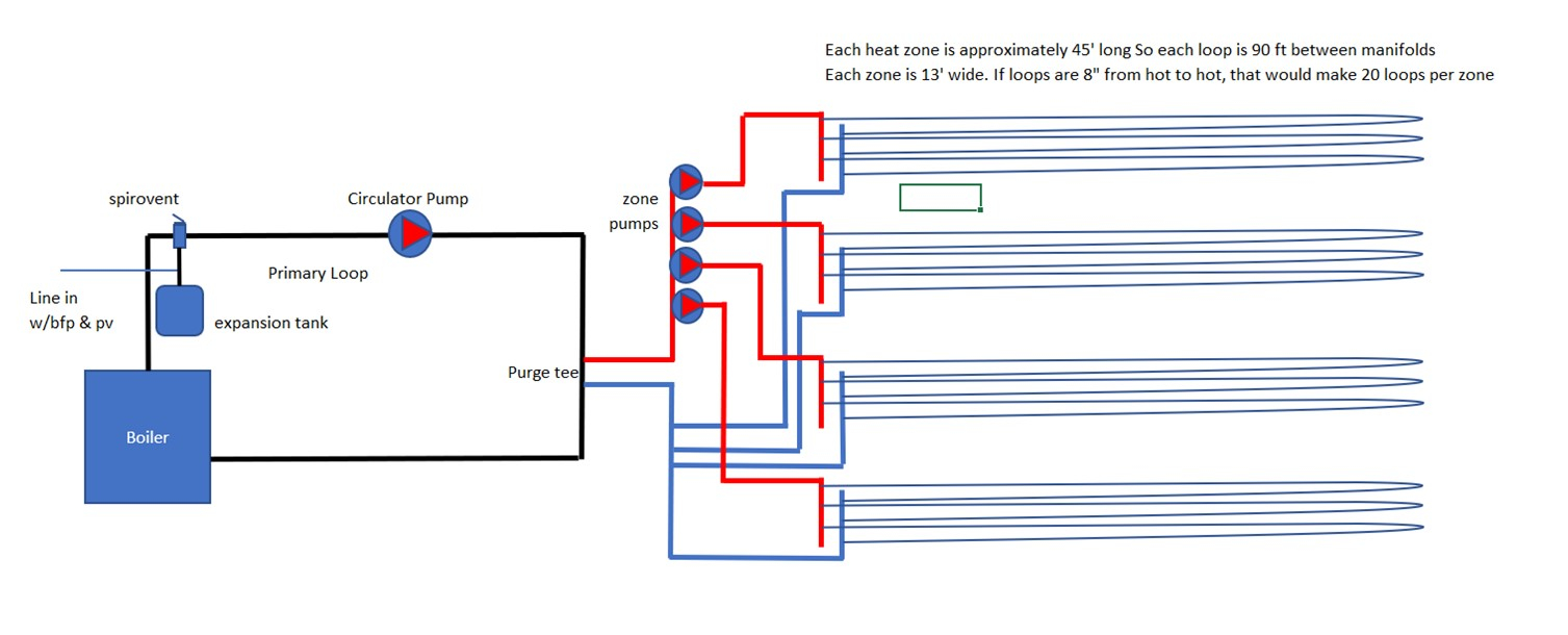
I've sized the zone pumps at 3.5 GPM/13' head which puts it in the wheel house of a Grundfous UPS 15-58.
What criteria do I consider to determine the size of the primary circulator?
- With close spaced purge tee I assume the flow of the primary pump is not related in any way to the flow of the zone pumps?
- I could figure the head of the primary loop with a little calculation, but what determines the rate of flow I need?
Thanks!
Comments
-
What is the total load you are trying to move from the boiler to the system on design day?
So the primary loop needs to be able to circulate that many BTU/ gpm around the circle.
Often the head is low, gpm high, so it is an odd circ to size.
You may want a boiler return protection function, how are you controlling the temperature to the loops?Bob "hot rod" Rohr
trainer for Caleffi NA
Living the hydronic dream0 -
As we discussed in another thread on this project, it's almost impossible to know the btu req's on heating soil in a greenhouse. I want to heat 6" of soil to 70F with an air temp of 40F. Air temp is regulated by forced air. Hydronic system is for root zone only.hot_rod said:What is the total load you are trying to move from the boiler to the system on design day?
So the primary loop needs to be able to circulate that many BTU/ gpm around the circle.
Often the head is low, gpm high, so it is an odd circ to size.
You may want a boiler return protection function, how are you controlling the temperature to the loops?
So what I did is took the 142k BTU the boiler can put out and divided it between the 4 heat zones for a total potential max load of 35k/zone or 58btu/ft². This seems quite high, but my logic is that I want the capability to move that if it is required. I'm open to better ideas.
I'm assuming a delta T of 20. Water temp is something I'll have to play with but I was figuring on 160/140 to start with.
My primary loop is 1¼ and secondary is 1".
On my last thread about this people were suggesting mixing valves of various kinds, but I have a hard time figuring that out too. I'm doing all copper and pex, no pvc. Do I need to mix the temp down for the zones?0 -
But to make it simple, should I size my primary circulator to move the same GPM as all my zone circs combined? so if they each pull 3.5gpm, should I size the primary for 21? Or is my thinking off on that...hot_rod said:What is the total load you are trying to move from the boiler to the system on design day?
So the primary loop needs to be able to circulate that many BTU/ gpm around the circle.
Often the head is low, gpm high, so it is an odd circ to size.
You may want a boiler return protection function, how are you controlling the temperature to the loops?0 -
Are your zone tubes directly in soil or under tables? I've considered trying to solve this kind of a design problem before. The conduction transfer of heat into the soil changes with delta T, water content, soil type and compaction. Just because you pump water capable of moving x numbers of btu's doesn't mean the heat will transfer out of the tubing fast or evenly. High flow in the zone tubes would give small delta T's (even heating) I would think good low temperature control of zone tubes would be desired. At 160-140F temperatures there would be a certain sized bio kill zone around the tubes in soil. Injection mixing, an adjustable thermostatic 3 way valve or a motorized 3 way valve that was controlled by an outdoor reset might be good to both protect your boiler and precisely control water temperatures in the zone loops.
Boiler loop primary pump sizing is typically 1 gpm per 10k btu input, with cast iron it can be less. A 3 speed up15-58 gives you some tuning options. If the zone load is smaller the boiler loop will just heat up and cycle off the boiler controller. Low flow would be fine for that but if the heat is being transferred out of the tubes well and the return water is coming back cooler, a higher flow boiler loop might be better. I had a smaller design problem and considered using masonry tile backer strips as heat spreader plates in the bottom of deep trays.0 -
If the boiler output is 142k,? then the primary loop would flow 14 gpm
Being a cast iron boiler you need to protect it from cold return and mix down the supply to the beds
A 4 way mix valve with control makes that a simple task
Here is one optionBob "hot rod" Rohr
trainer for Caleffi NA
Living the hydronic dream0 -
hot_rod Is a 4 way mixer just always a better arrangement. No close Tee's piping and better flow specs?0
-
With a low pressure drop boiler and his large tube, it could be a single pump system
hHis primary secondary piping would still need mixing and boiler protection. A 4 way makes it safe and simple
Injection mix is nice also, but it takes 3 pumps and a control. I think this Taco has everything on the valve ?Bob "hot rod" Rohr
trainer for Caleffi NA
Living the hydronic dream0 -
Primary only down to 140F. I was asking about 3 vs 4 way. 4way is just more elegant, though a 3-way will do the same thing. 4ways allow for higher flow rates on both sides.0
-
The main difference is the 4 way has two mixing points always. So it can be doing two jobs in one valve.
If you have a high pressure drop boiler, best to use two circulators, Fig 6.12,
I like manual (dumb) 3 way mix valves for proportional mixing. Fig 8.7 Set once and it tracks with the ODR, so an easy way to get a second mixed temperature on ODR without a motorized or thermostatic control.
So many way to do mixing, here is three valve options fig 6.13, and three injection mix options Fig 8.17.Bob "hot rod" Rohr
trainer for Caleffi NA
Living the hydronic dream0 -
I was thinking of the simple thermostatic remote probe 3 way. Yup, lots of ways.0
-
The zones will have ½" o2b pex spaced 8" hot to hot, 4" hot to return. Plan on burying ½ to 1" in sand. The flats to be heated are 5" deep. So we have quite a bit of soil to penetrate so slow flow is probably ideal. I've toyed with the idea of temperature based variable speed zone pumps but not sure if that's really necessary.Teemok said:Are your zone tubes directly in soil or under tables? I've considered trying to solve this kind of a design problem before. The conduction transfer of heat into the soil changes with delta T, water content, soil type and compaction. Just because you pump water capable of moving x numbers of btu's doesn't mean the heat will transfer out of the tubing fast or evenly. High flow in the zone tubes would give small delta T's (even heating) I would think good low temperature control of zone tubes would be desired. At 160-140F temperatures there would be a certain sized bio kill zone around the tubes in soil. Injection mixing, an adjustable thermostatic 3 way valve or a motorized 3 way valve that was controlled by an outdoor reset might be good to both protect your boiler and precisely control water temperatures in the zone loops.
Boiler loop primary pump sizing is typically 1 gpm per 10k btu input, with cast iron it can be less. A 3 speed up15-58 gives you some tuning options. If the zone load is smaller the boiler loop will just heat up and cycle off the boiler controller. Low flow would be fine for that but if the heat is being transferred out of the tubes well and the return water is coming back cooler, a higher flow boiler loop might be better. I had a smaller design problem and considered using masonry tile backer strips as heat spreader plates in the bottom of deep trays.
I plan to use zone pumps because of the difference in pipe length to the zones. I didn't want a closer zone to be favored by the pressure.
As far as protecting the boiler, what is the danger zone of returning temp? 5 to 10F Delta T? Or is the danger too cold of water returning?0 -
Help me understand the reason for mixing down to a lower temp. Is it just to ensure 20 degree drop before return?0
-
Sand is not the best conductor of heat, it is more of an insulator, but it can transfer heats somewhat.
Snuggle your toes into the sand on a hot sandy beach in July. Notice a few inches down it is not so warm. Sand has a very low specific heat, .1, concrete is .21, water 1.00
Heat capacity of sand is 9.5 btu/ cubic foot. wood is 17.6, water 62.4 to give you some examples.
Wet sand would be much more conductive. Just skipm the sand an put soil over the tubes?
The return temperature to that type of boiler needs to be around 130F within 10 minutes or so of running. If not you can corrode the heat exchanger and vent piping from condensation. So that boiler needs to run SWT of at least 150 or so, at a 20 °∆ that gets you return to a safe temperature.
You may not need Much more that 100- 120 to get those beds to the 60F? If there is no danger of the soil getting above 85F or so you can run higher temperature. At 160 SWT you may over-heat the plants. Try it and see, as you are in uncharted waters somewhat with this design.
With an adjustable mixing valve you have some room to adjust to the exact temperature you need or want. Typical thermostatic valves adjust from 85- 150° or so.
The 4 way valve I showed could be manually or automatic as far as temperature adjustment. It could also vary temperature to the loops based on air temperature, inside or outside the building. Or put the sensor in the soil and let it run.Bob "hot rod" Rohr
trainer for Caleffi NA
Living the hydronic dream0 -
I actually just watched your youtube presentation on coffee with Caleffi about mixing valves and scenarios they are used in. A lot of the graphics you shared here you explained there and I'm starting to wrap my mind around it. So if I went with the 4 way mix valve you picture, it looks like I could eliminate a primary loop pump altogether, am I right? Just let the zone circ's push/pull the system? Also, could I get away with only one delta P pump for all for zones and do zone valves even though 2 zones are 60 feet further down the greenhouse? It's possible I could design so they are more or less equidistant if I change my manifold locations...hot_rod said:If the boiler output is 142k,? then the primary loop would flow 14 gpm
Being a cast iron boiler you need to protect it from cold return and mix down the supply to the beds
A 4 way mix valve with control makes that a simple task
Here is one option
One more question about a mixing valve like the one you showed... Does it require another control box, or just sensors placed appropriately? Still trying to find good info on it.0 -
The sand should stay moist with the drainage from the irrigation. The tubing and substrate I'm mimicking some other grower's set ups. You may be right that 160 is overkill. I've just been around a few systems with 140 max (because of pvc components etc.) that could heat 2" of soil to 70F but struggled with deeper flats like the crop we are growing. So I want to make sure I can heat higher if I need to. But a mixing valve such as the one you suggested would give options as well.hot_rod said:Sand is not the best conductor of heat, it is more of an insulator, but it can transfer heats somewhat.
Snuggle your toes into the sand on a hot sandy beach in July. Notice a few inches down it is not so warm. Sand has a very low specific heat, .1, concrete is .21, water 1.00
Heat capacity of sand is 9.5 btu/ cubic foot. wood is 17.6, water 62.4 to give you some examples.
Wet sand would be much more conductive. Just skipm the sand an put soil over the tubes?
The return temperature to that type of boiler needs to be around 130F within 10 minutes or so of running. If not you can corrode the heat exchanger and vent piping from condensation. So that boiler needs to run SWT of at least 150 or so, at a 20 °∆ that gets you return to a safe temperature.
You may not need Much more that 100- 120 to get those beds to the 60F? If there is no danger of the soil getting above 85F or so you can run higher temperature. At 160 SWT you may over-heat the plants. Try it and see, as you are in uncharted waters somewhat with this design.
With an adjustable mixing valve you have some room to adjust to the exact temperature you need or want. Typical thermostatic valves adjust from 85- 150° or so.
The 4 way valve I showed could be manually or automatic as far as temperature adjustment. It could also vary temperature to the loops based on air temperature, inside or outside the building. Or put the sensor in the soil and let it run.0 -

So what do you think of this layout with the lone variable speed pump feeding all 4 zones (I forgot to illustrate zone valves) and the motorized 4 way mixing valve?0 -
Low zone flow can provide good delta T's if your loops have good heat conduction. The zone water has more time to transfer heat and comes out the other end cooler.
The result is that the first section of the heated area can overheat while the last section never gets warm enough. The better the conduction the worse the uneven heating is with low flow.
Good flow has less difference in temperature from the start of the loop to the end. It provides more even heating through out the whole loop.
Lower temperatures at good flow rates, for longer periods, makes for a more even controlled gentle heating. On the flip side if there's a lots heat loss in other areas of the system, longer run times mean more waste. Starts and stops are waste events. It's a game of compromises and mitigation.
The target zone water temperature will be found with soil type, moisture level and how cold it is, plant type by observation. High heat will drive moisture out of the soil faster, kill micro biology and maybe roots. I know timing with solar input can be important. Adding zone heat as the sun hits can be a problem. Over heating might not seem like it's a possible problem where you are doing what you're trying to do. You might be right. The greenhouses I've seen working had operators that did a lot of testing and adjusting for their use case and locality. They could have better control with investment and effort but they found what works for them and that's what they do. Manual adjustment temperature control and maybe programed pulses of heat to just keep the chill off rather than long low constant heat for the luxury plant spa experience. Automatic control will keep a much more precise temperature range but costs more in equipment tech and fuel. Consistent comfort costs. Glycol?0 -
I believe that Taco valve has all the control options built in, pipe it, select your output temperature, enable boiler return. I've never used one, but that is how I understand them. There are other brands, but those a 3 separate pieces. Maybe Taco will send me one so I can talk more knowledgeably
") I suspect it has tekmar brains, and I am familiar with that logic.
I suspect it has tekmar brains, and I am familiar with that logic.
The tighter the delta T from one end of the tube to the other, the higher the output. Because the average temperature in the tube increases. It's never about how much time the water "lingers" in the tube
Here is a graphic of that. All 3 examples get 110°F SWT, notice the flow (gpm) change and the output change.
This is true of any heat emitter, fin tube, radiators, fan coils, solar thermal, etc.
Changing, increasing SWT is a better way to increase output, it is more linear. At some point the gain from increasing flowrate alone, doesn't add much, see the graph. The red curve we call a hockey stick curve due to the shape. Notice big output change from 1/2 gpm to 1.5 gpm. Above 1.5 the curve levels off. Usually not worth chasing the output at those higher flows.
Now, tighter ∆ operation will require more pump power, so there is a trade off.
I'd get a multi speed pump and you could play around with flow rates and heat output.
The main thing is to assure your tubing can move all the boilers BTU to the dirt, and that the boiler is protected from cold running. Then play around with SWT to get the result you are looking for.
Another way to increase the output from the beds would be to lower the ambient temperature.
As I see it you have 12- 1/2" loops about 90' long? You could push 1 gpm per loop, so 12 gpm total. Pressure drop would be about 10' in a 100' loop of 1/2" pex
Add a few feet of head for piping, valves, etc, call it 12 gpm at 12' head.
I'd be inclined to go with a 26-99, the 15-58 may be a tad small.Bob "hot rod" Rohr
trainer for Caleffi NA
Living the hydronic dream0 -
Lingering water does create high delta's but never higher output or more even heating. Seeking high delta's at the compromise of output and evenness is a condensing boiler efficiency seeking thing.0
-
So what I'm hearing you say in general is that having options of flow rate and temp is going to give me the best possibility of finding that sweet spot of temperature transfer.hot_rod said:As I see it you have 12- 1/2" loops about 90' long? You could push 1 gpm per loop, so 12 gpm total. Pressure drop would be about 10' in a 100' loop of 1/2" pex
Add a few feet of head for piping, valves, etc, call it 12 gpm at 12' head.
I'd be inclined to go with a 26-99, the 15-58 may be a tad small.
I actually was thinking of more loops (see the first post in the thread) to 20 loops for close spacing and reducing head loss. Individual pots in the trays are 3.5" wide so a 4" spacing between supply and return should be as even as we can get. I think I read that 3.5" is the min radius of ½" Pex.
Here's my calculations. Correct any math or assumptions you see that are wrong.
If we are aiming for 10F delta T, the common formula would be 1GPM=5000BTU, am I right? But I think this is the big question - will we transfer those BTU at that rate...
But going with that formula...
If the max each heat zone can get from the boiler is 142k/4 =35k, then 7GPM (35k/5k) would be required for the flow of the zone if we are to deliver the max BTU.
Divide the 7 by 20 loops and we get 0.35 gpm/loop. But for figuring sake, lets round it to 0.5 gpm. That's the lowest flow the pressure drop table goes. see attached chart.
At that flow, manufacturer says that pressure drop in ½" pex is .51psi or 1.2' head (1psi = 2.3' head) over 100'. (I'm confused where you got 10' for 100' pex at 1 GPM?)
There's an additional ~150' or so of 1" Pex between the pump and the zone manifold (75 hot, 75 return). According to specs, this would take 10' head (4.3 psi) at 7 GPM.
So we still arrive at around 12' head for the zone. But only 7 GPM to achieve 10F delta T. (My initial post calling for 3.5gpm/13' head was based on 20F delta T - but I'm hearing you say we should probably tighten that up.)
Did I miss anything in those calc's?
0 -
So I looked around. I think I might go with a dumb mixing valve like this one. I'm gonna be baby sitting this thing like crazy so manual isn't too big of a deal and might actually be better till I get familiar with it.

0 -
Your bottle neck will be the 150" of 1" pex from the boiler to the beds. 8 to maybe 9 gpm is about what you can reasonably move within an acceptable velocity. I don't see you moving 145 BTU/ hr thru that 1" tube at 20∆. Use the free PPI calculator for those answers. Here is 8 gpm, 150' 1" pex has you just over 4 feet per second velocity. At 14' head.
That 4 fps is about the max. velocity comfort range for pex in a hydronic application.
So unless you can increase that tube size , you are looking at moving 80,000 btu/hr to the beds, at a 20 ∆. Is that enough?
You mentioned a 145K boiler? 145 input or output? If it is 145 input X 85% = 123,000 output that you have available.
Going to a 30∆, 8 gpm could get 120K
Without a load calc number and some temperature design criteria, to shoot for, we are just spitballing here.
The load calc tells you what size boiler, what size pump, what size tube, how many loops are workable. You are kinda backing into this design.
If the boiler size, and that distribution tube size is set in stone, may as well just adjust the loops to what you are going to be able to make happen.
Bob "hot rod" Rohr
trainer for Caleffi NA
Living the hydronic dream0 -
.35gpm with good conduction could be a higher delta T. With less conduction delta's might be very small. It sounds like you are copying a working technique so conduction must be good enough to warm what's needed evenly enough. Colder nights might need wetter sand and more flow to get more BTU's out of the pipe. Are these 75' runs of pex well insulated and dry? Flexibility in flow design will let you trim to your conditions. Is this really just one controlled zone with multiple branches or are these "zones" thermostat-ed? If you are multi-zoning with valves don't forget the head loss of the zone valve itself. A 1" 7.5 cv valve @8-9gpm will add another 2.4++ft. muli-zoning can help spread out what 1" pex can deliver. One zones off cycle is another's on but a good design can deliver what's needed to all zone's at once, at design OD temperatures.
From your first drawing you had 4 zones with 20 loops on each. 4x9gpm per zone is 36gpm. placing the mixing valve closer to the zones and pumping 180F out and 140F back @ 7 gpm gets you 140kbtu. Getting 36 gpm through a 1.5" 4way mixer is doable near 2.5ft of added head. Zone head near 8ft and 75' runs under 12ft @7gpm. 75' is a long loss to waste run at high temp.
0 -
No, no, no. Let me be a little clearer. The 150' of 1" pipe was from a single zone pump to a single zone. Only need 35k to go to an individual zone. That distance is only necessary for the 2 farthest zones unless I try to balance them. But regardless, 150' of 1" supply/return piping would be for a single zone (35k btu) not for all four.hot_rod said:Your bottle neck will be the 150" of 1" pex from the boiler to the beds. 8 to maybe 9 gpm is about what you can reasonably move within an acceptable velocity. I don't see you moving 145 BTU/ hr thru that 1" tube at 20∆. Use the free PPI calculator for those answers. Here is 8 gpm, 150' 1" pex has you just over 4 feet per second velocity. At 14' head.
That 4 fps is about the max. velocity comfort range for pex in a hydronic application.
And yes the boiler is 143k output/175k total. See attached plate pic. Or do I go by the 124k water btu?
I know I'm backing into this, but the people I've talked to with some experience greenhouse floor heating don't see a problem with the load. The details I'm trying to work out are what it takes to deliver that load. I think I have my answers for the most part, thanks. I think I'll go with the bigger zone pumps as you suggested, at least for the further zones, use the mixing valve I posted above, remove the local circulation for the boiler loop, the play with it to death to optimize the set up. Thanks for taking the time to help!0 -
Thank you for your input. I had considered going with insulated pex for the long runs, but have moved away from that Idea due to cost and availability. They would be running under other heated zones so I was thinking of burying them 1-2' down. I know I'll lose some heat and that it might affect the zone above it. I thought too about going the poor man's rout and filling around the pipe with some styrofoam or something similar. Do you have any suggestions?Teemok said:.35gpm with good conduction could be a higher delta T. With less conduction delta's might be very small. It sounds like you are copying a working technique so conduction must be good enough to warm what's needed evenly enough. Colder nights might need wetter sand and more flow to get more BTU's out of the pipe. Are these 75' runs of pex well insulated and dry? Flexibility in flow design will let you trim to your conditions. Is this really just one controlled zone with multiple branches or are these "zones" thermostat-ed? If you are multi-zoning with valves don't forget the head loss of the zone valve itself. A 1" 7.5 cv valve @8-9gpm will add another 2.4++ft. muli-zoning can help spread out what 1" pex can deliver. One zones off cycle is another's on but a good design can deliver what's needed to all zone's at once, at design OD temperatures.
From your first drawing you had 4 zones with 20 loops on each. 4x9gpm per zone is 36gpm. placing the mixing valve closer to the zones and pumping 180F out and 140F back @ 7 gpm gets you 140kbtu. Getting 36 gpm through a 1.5" 4way mixer is doable near 2.5ft of added head. Zone head near 8ft and 75' runs under 12ft @7gpm. 75' is a long loss to waste run at high temp.
Each zone will be statted. I plan to have a relay box near the boiler and zone pumps which would handle that.
At one point in this discussion I toyed with the idea of 1 circulator for the whole system and using zone valves. See my second diagram above. But no variable speed pump I could find really fit that bill. So just 4 zone pumps. Upon Hot_Rod's suggestion, I think the pumps will be grundfus UP 26-99'. The curves just work better especially for the zones on those long runs.
I think the manual mixing valve I posted above should at least give me some adjustable options and has a pretty high Cv. So I think I'll forego the primary loop circulator, use the 4 way mixing valve, and have 4 zone pumps do all the circulating.0 -
Also, when I got the used boiler it came with a large (to me) Bell & Gossett booster circulator. See pic. Is this designed to be a zone circulator or more something that is constantly running?


0 -
That is a fairly steep curve, high head circulator.Bob "hot rod" Rohr
trainer for Caleffi NA
Living the hydronic dream0 -
Check out the 0034e for a single pump option. 8 one inch pipes in the ground for an average of 55' is a chunk of loss. I guess if they are under heated space that's better. 16fthead @7-8gpm per zone with 1-1/4 4 way seems close. That B&G might do 2 zones at once but not more. The trouble you will find with a manual 4 way valve adjustments is that your load is not stable. As zones open and close the flow changes. As the loops heat up the delta changes and so will the supply temperature. A motor and controller will change the mix as needed to maintain a stable supply temperature with varying flow rates.0
-
I'm still not clear what you have for the boiler pump, since you indicated it is piped primary secondary.
IBC has a spec on options, did you use one of them?Bob "hot rod" Rohr
trainer for Caleffi NA
Living the hydronic dream-1


Categories
- All Categories
- 87.7K THE MAIN WALL
- 3.3K A-C, Heat Pumps & Refrigeration
- 59 Biomass
- 430 Carbon Monoxide Awareness
- 127 Chimneys & Flues
- 2.2K Domestic Hot Water
- 5.9K Gas Heating
- 121 Geothermal
- 170 Indoor-Air Quality
- 3.8K Oil Heating
- 79 Pipe Deterioration
- 1K Plumbing
- 6.6K Radiant Heating
- 396 Solar
- 16K Strictly Steam
- 3.5K Thermostats and Controls
- 56 Water Quality
- 51 Industry Classes
- 51 Job Opportunities
- 17 Recall Announcements