commercial bldg zone heating issues

Comments
-
Have you opened every bleeder to remove the air in the system?
Pictures of your system and the boiler would be helpful. 1
1 -
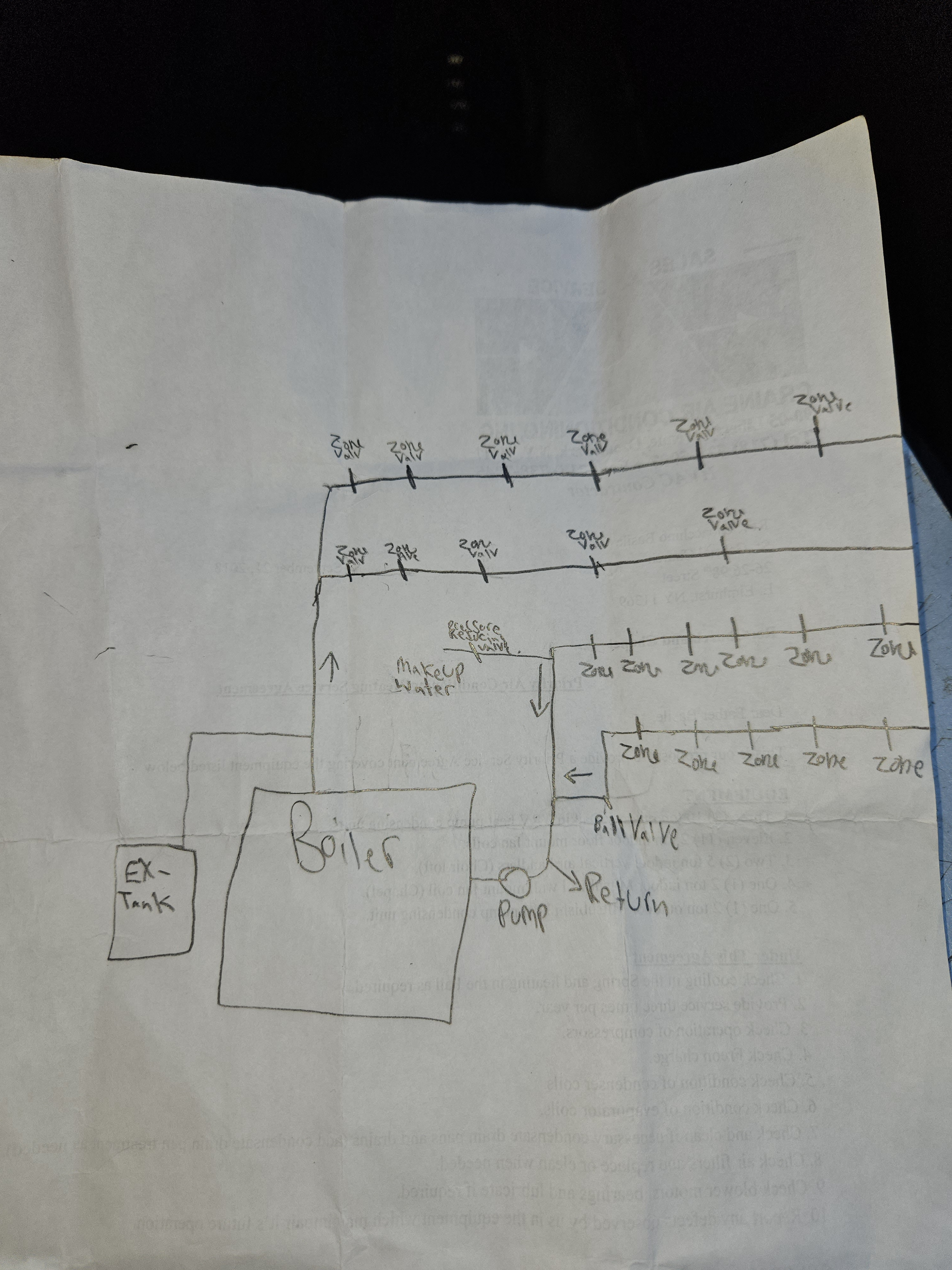
One problem I see is that according to your drawing the make up water is on the pump suction and the expansion tank is on the pump discharge.
It would be best (especially on a commercial job to move the circulator to the supply pipe off the boiler so it pumps away from the expansion tank. The make up water should be at the expansion tank or between the expansion tank and the pump inlet.
That may or may not be part of your issue.
To check the pump size we would need the boiler OUTPUT in BTU/hr. Pipe size and length also matters.
As @DanHolohan always says "if you bleed and don't get air it's not an air problem" it's a flow problem.
So do you get air or water when you bleed? If you are getting air it could be because of the circulator location. Do you have automatic air vents?
Is the expansion tank a steel compression tank or a bladder tank? 2
2 -
As Dan Holohan has taught us, you have to think like the water inside the pipes. I agree with both @leonz and @EBEBRATT-Ed pumping away would certainly be beneficial and a few photos (from far away) of the near boiler piping would be helpful.
If some of the zones are roughly fifty feet total run and others are three hundred feet total run, can you see which zone would prefer to pass through? Most likely the designer knew this and installed some sort of balance valves.0 -
yesleonz said:Have you opened every bleeder to remove the air in the system? Pictures of your system and the boiler would be helpful.leonz said:Have you opened every bleeder to remove the air in the system? Pictures of your system and the boiler would be helpful. every zone was throughly bleeded out , I closed off ball valve on the return line that stops flow to a section of the bldg which has 5 zones connected, I started getting flow to zones that was not getting flow before just to test , I will attach pics to get idea & more pics when I return back to job , my main focus to get heat to zones needed. 0
 -
it's a bladder tank , don't see any automatic vents , after some air on some zones , I got nothing but water seems like flow issue, as for the pump I got info , but not much pictures i.ll attach so you guys get idea , I will get pipe dia, & you mentioned length what length? myfocus is to supply heat to zones that needs it .EBEBRATT-Ed said:One problem I see is that according to your drawing the make up water is on the pump suction and the expansion tank is on the pump discharge. It would be best (especially on a commercial job to move the circulator to the supply pipe off the boiler so it pumps away from the expansion tank. The make up water should be at the expansion tank or between the expansion tank and the pump inlet. That may or may not be part of your issue. To check the pump size we would need the boiler OUTPUT in BTU/hr. Pipe size and length also matters. As @DanHolohan always says "if you bleed and don't get air it's not an air problem" it's a flow problem. So do you get air or water when you bleed? If you are getting air it could be because of the circulator location. Do you have automatic air vents? Is the expansion tank a steel compression tank or a bladder tank?


 0
0 -
Your boiler output shows you need to move about 46gpm.
Someone familiar with B&G pumps may know more about the rating of that pump. You need 46GPM at enough head pressure to push water through the zone with the largest head loss. (usually the longest run).0 -
How long is the longest run from the boiler? Measure (approximate) from the boiler to the farthest point and back to the boiler. This will help us determine if the correct pump is installed. In commercial buildings this could be as little as one hundred feet or as much as over one thousand feet.0
-
my rough guess would be its over 200ft from basment to the 2nd flr ,where there's issue with flow not sure if it's looped to any additional baseboards & then makes it back to boiler, if I was to close off supply ball valves to zones not needing heat, will this get heat to ereas needing heat ?ScottSecor said:How long is the longest run from the boiler? Measure (approximate) from the boiler to the farthest point and back to the boiler. This will help us determine if the correct pump is installed. In commercial buildings this could be as little as one hundred feet or as much as over one thousand feet.0 -
So if it's 200 feet each way, that would be 400 feet total. This would require about 24 feet of head. If I misunderstood, and t's 200 total, that would ne 12 feet of head.
Reason I asked is that your pump is only capable of delivering about 8 feet of head. I'm guessing your pump was replaced with the wrong model in the past.
Next question, what is the BTU load (heat loss of the building)? If you don't know, what is the output what is the boiler output (net IBR output)?
0 -
Nevermind, just read your tag from the boiler. 399,000 IBR out. Your series 100 pump is undersized. In simple terms, you need a bigger pump.0
-
I figured the pump was small , the way it was operating , any larger size model you can suggest that will push water to the furthest point with no issues .ScottSecor said:Nevermind, just read your tag from the boiler. 399,000 IBR out. Your series 100 pump is undersized. In simple terms, you need a bigger pump.0 -
With regard to pump sizing, we never size pumps based on internet posts. Instead we visit the site, do a quick heat load calculation, examine the pipe size, measure the distance of the longest run, examine the method the boiler is piped, check the voltage available and observe how restrictive the components of the system are. Really need to know if it approximately 200 or 400 feet for the longest run, it makes a big difference.
Taco is a sponsor of this site and they may be able to offer a model that would fit the bill.
With your building I'd hate to see a system with such a variable load (11 zones) use a constant speed pump. If you choose a properly sized single speed pump, you really need a pressure bypass valve.
Instead, we much prefer a variable speed pump that would automatically slow down when only a few zones are calling for heat. If more zones open, the pump would automatically speed up. The problem is the would require some re-piping.
All of the pumps I can think of that will do the job will not fit in the current pump location. Every model I look at is significantly longer from flange to flange. You might want to consider hiring a professional heating contractor to at least size the new pump. 1
1 -
ScottSecor said:With regard to pump sizing, we never size pumps based on internet posts. Instead we visit the site, do a quick heat load calculation, examine the pipe size, measure the distance of the longest run, examine the method the boiler is piped, check the voltage available and observe how restrictive the components of the system are. Really need to know if it approximately 200 or 400 feet for the longest run, it makes a big difference. Taco is a sponsor of this site and they may be able to offer a model that would fit the bill. With your building I'd hate to see a system with such a variable load (11 zones) use a constant speed pump. If you choose a properly sized single speed pump, you really need a pressure bypass valve. Instead, we much prefer a variable speed pump that would automatically slow down when only a few zones are calling for heat. If more zones open, the pump would automatically speed up. The problem is the would require some re-piping. All of the pumps I can think of that will do the job will not fit in the current pump location. Every model I look at is significantly longer from flange to flange. You might want to consider hiring a professional heating contractor to at least size the new pump.
if you are a heating contractor in New York city , can I contact you ?ScottSecor said:With regard to pump sizing, we never size pumps based on internet posts. Instead we visit the site, do a quick heat load calculation, examine the pipe size, measure the distance of the longest run, examine the method the boiler is piped, check the voltage available and observe how restrictive the components of the system are. Really need to know if it approximately 200 or 400 feet for the longest run, it makes a big difference. Taco is a sponsor of this site and they may be able to offer a model that would fit the bill. With your building I'd hate to see a system with such a variable load (11 zones) use a constant speed pump. If you choose a properly sized single speed pump, you really need a pressure bypass valve. Instead, we much prefer a variable speed pump that would automatically slow down when only a few zones are calling for heat. If more zones open, the pump would automatically speed up. The problem is the would require some re-piping. All of the pumps I can think of that will do the job will not fit in the current pump location. Every model I look at is significantly longer from flange to flange. You might want to consider hiring a professional heating contractor to at least size the new pump.0 -
There must be balancing valves somewhere?
Or it could be piped reverse return do the system self balances
I don’t see a 1/12 hp circ being adequate for gpm or head?
Bob "hot rod" Rohr
trainer for Caleffi NA
Living the hydronic dream0 -
I haven't ben back to the job site yet , when I go back i.ll take more pictures, & other info .& update , thanks0
-
also want to mention how can I get heat to the 2nd flr that really needs it for know ? what am trying to say is closing off supply & return for zones that don't need heat , will this force hot water to flow to 2nd flr radiaters ?0
-
Maybe? But if the circulator doesn't have the head, horsepower so to speak, to overcome the resistance on those longer runs you still may not get adequate flow to the remote heat emitters.nytech28 said:also want to mention how can I get heat to the 2nd flr that really needs it for know ? what am trying to say is closing off supply & return for zones that don't need heat , will this force hot water to flow to 2nd flr radiaters ?
You need some stable data on this job as a starting point. either calculations, or discover what has changed, what was removed when it was a working system. I would not just keep showing up with the next size pump as the trial and error method.Bob "hot rod" Rohr
trainer for Caleffi NA
Living the hydronic dream0 -
================================================================================================================================nytech28 said:
Good morning,
I have this hot water boiler with 11 zones, some zones are getting more heat than others.
I bled air out the all the zones. I was told by management they had 2 boilers piped together & nbsp; in past,
After 1 boiler failed they re-piped the plumbing to use as 1 boiler, know they are getting issue with zones getting less or no heat.
I will draw a diagram showing the current set up on boiler to get heat to zones where it's needed, if I was to close ball supply valves to some zones not needing heat, can this divert hot water to zones needed, I believe there is flow issue probably pump not strong enough or after repiping and any direction would be appreciated to get this fixed for now and correct what's needed later.
Can you provide us with pictures of the rest of the plumbing above and around the boiler?
Your boiler may very well have a cast air bubble baffle in the steam chest.
The air bubble baffle forces the air bubbles to the top of the boiler steam chest where the air eliminator allows the air to escape or using a properly sized Steel Compression Tank, Internal Air Separator and airtrol valve directs the air bubbles upward with a portion of the hot water from the Internal Air Separator to rise to the Airtrol Valve and into the steel compression tank where the air bubbles are absorbed and the water cools and falls back into the heating system.
With the picture you were so kind in providing enlarged I saw a sheet metal punch out circle that may very well cover an air vent tapping that is used to plumb in a very large automatic air vent or steel compression tank and airtrol valve easily.
I would at least lift the top skin off the boiler and turn it to see if there is a plugged tapping directly under the punch out plug in the top skin of the boiler and go from there.
If there is a tapping in the boiler purchase the correct size air eliminator for the system making sure it is plumbed with a long pipe nipple, a globe valve, a short pipe nipple, union, pipe nipple and lastly the air eliminator.
So, if you find a plugged tapping under the top skin of the boiler assuming it is 3/4" N.P.T., you need the following parts;
1. 3/4" pipe nipple-the longer the better being 6"-12" to allow you to assemble it all in the pipe vise before you screw it into the boiler tapping.
2. 3/4" N.P.T. union
3. 3/4" by 6" pipe nipple
4. 3/4" N.P.T. female/female globe valve
5. 3/4" by 4" N.P.T. pipe nipple
6. 3/4" N.P.T. coupler
7. NOW you could do number 7 in one of two ways:
3" N.P.T. pipe nipple
3/4" N.P.T. coupler
3/4" boiler drain
This way you could purge the air out of the system when it is cold using a garden hose.
OR install a high quality automatic air eliminator right after the coupler being part number 6 and in the eventuality that the air eliminator fails you can replace it quickly by simply shutting off the globe valve,
breaking the union, removing the air eliminator and removing it from the half union pipe nipple and
coupler then installing the new one with a tiny bit of pipe dope past the first thread then putting it all back together and then reconnecting it to the union in the air baffle tapping on the boiler steam chest.
0 -
you're pumping to your expansion tank,
move your tank connection to your feed connection, or to before your circulator,
this may fix all your issues
where is your air separation and air vents?known to beat dead horses0 -
If the pump is not large enough which is what some of us suspect fooling with air bubbles and venting at this point is a waste of time.
If you install a larger pump (flow and head) your really need to consider pumping away from the expansion tank.
The only way i can see this system working (if it ever worked) the way it is constructed now is with a boiler that is way oversized for the load and a circulator that is the right size for the load.
I doubt they installed it that way because it looks like 2" copper tubing for the piping which matches the boiler flow requirements of 46 gpm.0 -
there is no air vents or air separate installed at the boiler piping, only air vent I see is by some radiaters , will be returning back to jobsite & will take more info & pictures .0
-
I aprecaite the comment , i.ll have to return back & take more info & updateleonz said:Good morning, I have this hot water boiler with 11 zones, some zones are getting more heat than others. I bled air out the all the zones. I was told by management they had 2 boilers piped together & nbsp; in past, After 1 boiler failed they re-piped the plumbing to use as 1 boiler, know they are getting issue with zones getting less or no heat. I will draw a diagram showing the current set up on boiler to get heat to zones where it's needed, if I was to close ball supply valves to some zones not needing heat, can this divert hot water to zones needed, I believe there is flow issue probably pump not strong enough or after repiping and any direction would be appreciated to get this fixed for now and correct what's needed later.
================================================================================================================================ Can you provide us with pictures of the rest of the plumbing above and around the boiler? Your boiler may very well have a cast air bubble baffle in the steam chest. The air bubble baffle forces the air bubbles to the top of the boiler steam chest where the air eliminator allows the air to escape or using a properly sized Steel Compression Tank, Internal Air Separator and airtrol valve directs the air bubbles upward with a portion of the hot water from the Internal Air Separator to rise to the Airtrol Valve and into the steel compression tank where the air bubbles are absorbed and the water cools and falls back into the heating system. With the picture you were so kind in providing enlarged I saw a sheet metal punch out circle that may very well cover an air vent tapping that is used to plumb in a very large automatic air vent or steel compression tank and airtrol valve easily. I would at least lift the top skin off the boiler and turn it to see if there is a plugged tapping directly under the punch out plug in the top skin of the boiler and go from there. If there is a tapping in the boiler purchase the correct size air eliminator for the system making sure it is plumbed with a long pipe nipple, a globe valve, a short pipe nipple, union, pipe nipple and lastly the air eliminator. So, if you find a plugged tapping under the top skin of the boiler assuming it is 3/4" N.P.T., you need the following parts; 1. 3/4" pipe nipple-the longer the better being 6"-12" to allow you to assemble it all in the pipe vise before you screw it into the boiler tapping. 2. 3/4" N.P.T. union 3. 3/4" by 6" pipe nipple 4. 3/4" N.P.T. female/female globe valve 5. 3/4" by 4" N.P.T. pipe nipple 6. 3/4" N.P.T. coupler 7. NOW you could do number 7 in one of two ways: 3" N.P.T. pipe nipple 3/4" N.P.T. coupler 3/4" boiler drain This way you could purge the air out of the system when it is cold using a garden hose. OR install a high quality automatic air eliminator right after the coupler being part number 6 and in the eventuality that the air eliminator fails you can replace it quickly by simply shutting off the globe valve, breaking the union, removing the air eliminator and removing it from the half union pipe nipple and coupler then installing the new one with a tiny bit of pipe dope past the first thread then putting it all back together and then reconnecting it to the union in the air baffle tapping on the boiler steam chest.0


Categories
- All Categories
- 87.7K THE MAIN WALL
- 3.3K A-C, Heat Pumps & Refrigeration
- 59 Biomass
- 430 Carbon Monoxide Awareness
- 127 Chimneys & Flues
- 2.2K Domestic Hot Water
- 5.9K Gas Heating
- 121 Geothermal
- 170 Indoor-Air Quality
- 3.8K Oil Heating
- 79 Pipe Deterioration
- 1K Plumbing
- 6.6K Radiant Heating
- 396 Solar
- 16K Strictly Steam
- 3.5K Thermostats and Controls
- 56 Water Quality
- 51 Industry Classes
- 51 Job Opportunities
- 17 Recall Announcements