Magnetic dirt separator location in a primary / secondary system

I have a Buderus GB142-60 supplying DHW to an indirect tank on a primary loop and a hydronic air coil on the secondary loop. The pump on the DHW primary loop just died. I am considering an ECM pump for replacement. I want to install a magnetic dirt separator in the system to protect the new pump. The system has 2 air separators already -- one in the boiler and one by the expansion tank, on the secondary loop supply side.
The system also has a cast iron hydraulic separator / low loss header. The primary loop comes out between the boiler supply and the low loss header. This is where the primary loop pump is located, pumping away from the boiler supply side. The return for the primary loop, likewise, enters between the boiler and the low loss header, as it should.
The secondary loop exits and enters the bottom of the low loss header on supply and return, respectively, as it should. The pump for the secondary loop is located next to the hydronic air coil, about half way through the circuit. I am not sure if it is pumping into the coil or pulling out of the coil.
The boiler also has a pump between the hydraulic separator and the boiler return, pumping into the boiler. This is on when the secondary loop is active, but off when the primary loop is active.
The boiler pump is non-ECM, the hydronic air coil pump is non-ECM. The dead, primary, DHW pump is the one I am replacing with an ECM pump. However, I will probably be replacing the secondary loop, hydronic air coil pump with an ECM pump this summer.
My understanding is that it is typically better to have the magnetic dirt separator on the return side of he boiler. My question is whether it is better to have the separator on the primary loop or secondary loop.
The primary loop may be avoiding some of the gunk by pulling above the cast iron hydraulic separator. The secondary loop may be getting more of that gunk. But the pump I want to protect is being added to the primary loop. Then there is the question of protecting the pump in the secondary loop if I replace it with an ECM motor this summer.
The primary loop is circulating 190 degree water X times per day, all year. The secondary loop is circulating 140ish degree water more frequently during the heating months and not circulating during the non-heating months (which is about 6 months, or fewer, where I am located, in Minnesota).
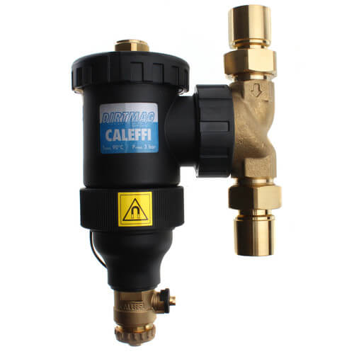
In case it matters, I am considering the Caleffi DIRTMAG (NA545396). The primary loop should end up with a maximum of 10 GPM (which is what the DIRTMAG is rated for). The secondary is pushing less water currently, I believe. From memory, I think the head loss of the DIRTMAG is about 1.4 ft at that flow rate. If a model different than the NA545396 is better for my application, please let me know.
Recommendations on where you would put the magnetic dirt separator on a system like this?
Thanks,
David
Comments
-
maybe post a picture showing the boiler and all the surrounding piping to save a 1000 words yet to comeknown to beat dead horses1
-
symantics, but,
by definition, your primary loop is the loop with the expansion tank on it,
the boiler may inject into the primary, or be part of it,
the secondary(ies) would be your zones, airhandler, domestic,
the dirtmag would go on the primary, and protect and clean all,
or aim it for you new circ, and or add more for all circs$$$$$$
lets see the picture
known to beat dead horses0 -
My expansion tank is on the air handler circuit. DHW is on the other circuit.neilc said:symantics, but,
by definition, your primary loop is the loop with the expansion tank on it,
the boiler may inject into the primary, or be part of it,
the secondary(ies) would be your zones, airhandler, domestic,
Photos coming up.
0 -
Here are 8 pictures (AKA 8000 words) that should help.

System layout:
Note: The installer put the expansion tank on the air handler circuit rather than hanging off the low loss header, as shown in the diagram.
In my photos, what I label as primary, I believe you would simply call a priority secondary zone. Since the boiler turns off its primary pump, the DHW zone is kind of acting like a primary loop (at least in my mind ).
Supply and Return near the boiler photos:


Supply and Return tubing photos:

Thanks,
David
0 -
that domestic motor is to be mounted horizontally, like your boiler pump, horizontally.
your trapping air at the top bearing mounted up like that, or dirt at the bearing if you swing it 180 down,
I guess I would add the dirt mag on the most active loop you have there,
Domestic?
where does the makeup water feed tye in?
I can't see it with the compression tankknown to beat dead horses1 -
the motor orientation may be the bigger issueknown to beat dead horses
 2
2 -
Yes. And that may be what finally did in the motor. That's the way the installer put it in 2011. I plan to rotate the flanges when I install the new pump.neilc said:that domestic motor is to be mounted horizontally, like your boiler pump, horizontally.
your trapping air at the top bearing mounted up like that, or dirt at the bearing if you swing it 180 down,
That's the most active one in the summer. The hydronic air loop is most active in the winter.neilc said:
I guess I would add the dirt mag on the most active loop you have there,
Domestic?
As you can see from the photos, there is no way to add it between the boiler and the low loss header, which would probably be ideal.
From what you said before, I guess if I am going to add other ECM pumps in other loops, then I should have a magnetic dirt separator on each loop? Is that how it is typically done when circuits have their own pumps?
The system is a closed loop and never leaks and never needs make-up water.neilc said:
where does the makeup water feed tye in?
I can't see it with the compression tank")
I manually add make-up water with a separate transfer pump, into one of the spigots on the system.
It has actually done pretty well. The expansion tank went bad some years back, so that obviously messed with the pressure. And sometime in the past year, the air vent built into the boiler went south. I noticed that I was losing pressure, but wasn't sure why. I recently tracked it to that. Apparently they are known for failing. I already ordered and have the replacement part. I was waiting until summer to work on the system, but then the pump died after I bumped up the pressure yesterday. Best guess is air or magnetite did him in. At one point there was a bang and his lights don't even come on now.
We're getting by on an electric on-demand heater that I put in on the downstream side of the water heater back in 2011 when my old system died (Lennox CompleteHeat). I don't want to get by on that until summer, so I'll be replacing the DHW pump soon. When I do that, I'll replace the boiler air vent, rotate the DHW pump flanges, install the new DHW pump, put a check valve downstream of that a bit (the replacement pump doesn't have a built in check valve, and I don't even know if the original pump had one), and install the magnetic dirt separator. I'll also be flushing the whole system with cleaner and putting inhibitor in the fill water.
I've only used distilled water in the system (and inhibitor). I think that's one of the reasons the boiler is still going strong (knock on wood!!!!).
I really appreciate you taking a look and giving me your recommendations.
Do you see anything wrong with the expansion tank being part of the air handler loop instead of hanging off the low loss header, like Buderus shows in their diagram?
Thanks,
David
0 -
let's see if I can do this multi quote thing,
If you shop wisely there are circs with a 4 way flanges,davidd said:
Yes. And that may be what finally did in the motor. That's the way the installer put it in 2011. I plan to rotate the flanges when I install the new pump.neilc said:that domestic motor is to be mounted horizontally, like your boiler pump, horizontally.
your trapping air at the top bearing mounted up like that, or dirt at the bearing if you swing it 180 down,
I would still aim for the most consistent, year round activity of the Domestic,davidd said:
That's the most active one in the summer. The hydronic air loop is most active in the winter.neilc said:
I guess I would add the dirt mag on the most active loop you have there,
Domestic?
interested in other opinions here , , ,
I would say one is plenty,davidd said:From what you said before, I guess if I am going to add other ECM pumps in other loops, then I should have a magnetic dirt separator on each loop? Is that how it is typically done when circuits have their own pumps?
do you know you have an actual magnetite / irons issue?
where it is it does connect back to the header (unless you shut that ball valve), and all circs look like they pump away, not sure I see the harm in its location,davidd said:Do you see anything wrong with the expansion tank being part of the air handler loop instead of hanging off the low loss header, like Buderus shows in their diagram?
hate when that happensdavidd said:At one point there was a bang and his lights don't even come on now.
known to beat dead horses0 -
really any place in the piping where all the flow will pass. Return before the boilers and pumps ideally. They are multiples devices so it takes a day or so to start showing evidence of what it has pulled.Bob "hot rod" Rohr
trainer for Caleffi NA
Living the hydronic dream0 -
Looks like it worked to me.neilc said:let's see if I can do this multi quote thing,
I was eying one of those, but that particular one isn't going to give me the GPM I want. And the one I think I'm going with doesn't come in a 4 way configuration. That would have been the easier way to drop in a new motor though. I'll move the flanges and then I'll be ready for replacing the pump again, hopefully in the distant future.neilc said:
If you shop wisely there are circs with a 4 way flanges,davidd said:
Yes. And that may be what finally did in the motor. That's the way the installer put it in 2011. I plan to rotate the flanges when I install the new pump.neilc said:that domestic motor is to be mounted horizontally, like your boiler pump, horizontally.
your trapping air at the top bearing mounted up like that, or dirt at the bearing if you swing it 180 down,
I'm also starting to ponder some more "out there" ideas. For instance, if I were to replace that low loss header (which apparently is steel...I thought it was cast iron) with a brass or stainless steel model, that also has a built-in magnetic dirt separator in it, I would not only catch the junk at the nexus of all the piping, I would also reduce what is possibly my biggest contributor to the magnetite and rust.neilc said:
I would still aim for the most consistent, year round activity of the Domestic,davidd said:
That's the most active one in the summer. The hydronic air loop is most active in the winter.neilc said:
I guess I would add the dirt mag on the most active loop you have there,
Domestic?
interested in other opinions here , , ,
It has always seemed odd to me that they took an aluminum heat exchange boiler and then put all that ferrous stuff right below it. Black iron/steel pipes and a steel low loss header, and plumbed with iron connectors. And even though my header hasn't had a problem leaking, I know from reading about other installs that those connection points are a weakness.
I've never looked into sizing a hydraulic separator. I'd have to figure out the right size to replace the one that's there. This isn't something I'm going to do when I replace the pump in the coming weeks, but it is something I could try to do this summer.
I'll start another thread here on a ferrous-free system. It doesn't seem to me like that's something the market sees a lot of demand for. I imagine it would add a lot to the cost of a system.
I don't have a cast iron boiler and radiator system to compare against, but when I flushed the system yesterday, I had a lot more magnetite coming out than I liked seeing. And not just suspended in water. It was settled in somewhere and came out in thick batches. That darn Buderus air vent dying must have really done a number on my water quality.neilc said:
I would say one is plenty,davidd said:From what you said before, I guess if I am going to add other ECM pumps in other loops, then I should have a magnetic dirt separator on each loop? Is that how it is typically done when circuits have their own pumps?
do you know you have an actual magnetite / irons issue?
The only iron containing items I know that I have in the system are:
- Old Ironside -- The Taco pump on the hydronic air coil that came with the original CompleteHeat system. I'm guessing he is almost 30 years old.
- Blowhard -- The expansion tank. He's several years old.
- Dearly Departed -- The cast iron Taco pump who met his maker. He was installed in 2011.
- Rusty -- The low loss header manifold and connected doo-dads. This is probably my biggest source of iron.
Yes, that's the one problem I noticed. I wanted to shut off the hydronic loop when I was flushing the system, but I had to open it up before pressurizing, because I'll blow the relief valve if the hydronic loop isn't open to the low loss header.neilc said:
where it is it does connect back to the header (unless you shut that ball valve), and all circs look like they pump away, not sure I see the harm in its location,davidd said:Do you see anything wrong with the expansion tank being part of the air handler loop instead of hanging off the low loss header, like Buderus shows in their diagram?
If I had it hanging off the low loss header, I thought maybe it would see hotter water than where it is now, and the air separator might work a little better.
He lived a reasonably long life, especially considering he was installed in an incorrect orientation. But this is exactly why I try to do as little to the system in the winter as I can. Hindsight is 20/20, but I should have left the crud in the system and just added some makeup water. I took the risk of draining, flushing, and refilling, and it pushed him over the edge. If I had it to do over again, I would have either just added the make-up water, or I would have taken the pump out and checked and cleaned it when I saw all that black gunk come out. Lesson learned.neilc said:
hate when that happensdavidd said:At one point there was a bang and his lights don't even come on now.
It is too bad that a replacement circuit board and cartridge cost more than a new version of the whole pump. I still haven't taken the pump out. It is theoretically possible that the board died and the cartridge is okay, but I don't know what made the bang noise. It sounded like a pipe burst and I immediately listened to see where the water was going to come pouring out of. I don't know why the cartridge dying would break the circuit board.
Thanks again for your help!
0 -
The problem with this system is that it doesn't have a central point where all the flow will pass where I can plumb in the magnetic dirt separator. The only idea I've thought of for that is to replace the OEM low loss header and related pipes with a combination hydraulic separator with a built in magnetic separator feature. I haven't searched yet to see if they make these in brass or stainless steel. Not that it would have to be non-ferrous, but if I can cut down on my iron containing items, it could reduce the level of "badness" in my water in the future.hot_rod said:really any place in the piping where all the flow will pass. Return before the boilers and pumps ideally. They are multiples devices so it takes a day or so to start showing evidence of what it has pulled.
0 -
limp thru the next month to summer,
then repipe the entire thing to the diagram above your pictures (?)known to beat dead horses0 -
A 4 in 1 Sep could really clean up your piping
Get you high performance air, dirt, magnetic and hydraulic separationBob "hot rod" Rohr
trainer for Caleffi NA
Living the hydronic dream1 -
The only difference between my system and the diagram is the location of the expansion tank. And the fact that I don't think there is a check valve in the DHW pumpneilc said:limp thru the next month to summer,
then repipe the entire thing to the diagram above your pictures (?)
I do plan on moving some stuff around this summer, but I don't want to get by on the wimpy electric on-demand water heater until the heating season is over.
This is definitely a case of doing some work now and more work in the summer.0 -
Thanks for the validation of that idea. Do you have any that you can recommend? Possibly that are brass or stainless steel, or some other non-ferrous material?hot_rod said:A 4 in 1 Sep could really clean up your piping
Get you high performance air, dirt, magnetic and hydraulic separation
Also, how would I go about sizing one to match the size of the OEM low loss header that came with the Buderus boiler?0 -
There should not be an issue with steel or iron in hydronic systems. Cast iron boilers, steel expansion tanks circulators, etc.
If you have ongoing corrosion that indicates oxygen is somehow getting in on an ongoing basis.
Non barrier tubing, or an air vent allowing air in?
Corrosion inhibitors should deal with small amounts of O2 ingress.
With any aluminum in the boiler you need a specific inhibitor.
Can’t go wrong with Caleffi components, steel seps.
Sep is sized by the flow rate on which ever side has the highest gpm. 1-1=4 should do it, maybe even 1” if you are in the 8-10 gpm range.Bob "hot rod" Rohr
trainer for Caleffi NA
Living the hydronic dream1 -
Sep is sized by the flow rate on which ever side has the highest gpm. 1-1=4 should do it, maybe even 1” if you are in the 8-10 gpm range.range.
I'm not following the 1-1=4 part@hot_rod?Nevermind. I understand now. You're saying a 1 1/4" size should satisfy my needs.
0 -
Also, the GB142-60 came with a Grundfos UP1558FC pump to be used for the primary boiler loop. In the manual, it states:
...
GB142/60 = 20 GPM (76 LPM) - High speed for Grundfos
UP1558FC pump...
What is odd is that pump only goes up to 17 GPM without any head. If my memory is right, I think the boiler has about 4 feet of head. Looking at the pump curve, it looks like speed level 3 would give me about 14 GPM on the primary side. My secondary side is slower right now, through the hydronic air coil. I don't know what kind of flow I'll be pushing when I put in under floor heat for a couple rooms with frozen ground right under them and a vaulted ceiling above , with the radiant loop being separate from my boiler loop, and losing some heat through a heat exchanger (needed, because I'll be running an antifreeze mixture in the radiant loop).
0 -
The opposite actually, too small would induce flow across the two sides.
A 4 pipe buffer tank
is basically a supersized hydraulic separator.
Bob "hot rod" Rohr
trainer for Caleffi NA
Living the hydronic dream0 -
I think we are saying the same thing. Let me rephrase it.
If you use a hydraulic separator that is bigger than you need, is it true that this will not cause problems?
If you use a hydraulic separator that is smaller than you need, is it true that this will cause problems?
On a related note, are you able to tell me whether the DIRTMAG (not the hydraulic separator, but just the magnetic dirt separator) that has the black composite body has any steel in it? I'm looking at ordering one of these for my system. One of the sellers states that it has steel in it, but I'm thinking that might be a misprint.

Thanks!
David
0 -
No steel in that model. It is only up to 1" size however. 12 gpm comfort range at 4 fps.
Bob "hot rod" Rohr
trainer for Caleffi NA
Living the hydronic dream0 -
Thank you. I read those documents previously. I appreciate all the literature Caleffi provides with their products. I just wanted to double check with you, since the reseller listed steel on their website.
10 GPM would be fine for me. That's my target GPM for my DHW loop. I'm not getting that currently, because of head losses and the pump being used. I was going to get a new, bigger, ECM pump, hence the need for the magnetic dirt separator.
As it turns out, I took the Taco 008 pump out last night, separated the housing, and the impeller spun fine. I rigged up a way to plug it in, with a switch, to see if it would fire up. Fired up just fine. Impeller moved just fine.Some head scratching.
From earlier in this thread, when discussing it with @neilc, I mentioned that I had flushed and refilled the system, and when running a test with the DHW loop, there was a bang. When I looked at the pump, one of the lights was flickering and went out. I assumed the cartridge failed, but I didn't know why that would affect the circuit board.
When I isolated the pump with the flange shut off valves (which, by the way, are the rotating type, so I didn't have to re-sweat them to get the pump oriented in the right direction….the valve handle tips do hit the bolts on the flanges, so I can't have the pump perfectly level, but pointing down a tiny bit is probably better than pointing straight up like it had been), and pulled the pump out, I noticed something sticking out of the ball valve socket on the upstream side. I grabbed it and pulled it out of the socket, but it dropped into some stuff on the floor and I haven't tried to find it yet. It felt like a thin strip of metal. It was about 2-3 inches long.
My best guess is that came loose from the Buderus steel low loss header or from my previous expansion tank that failed. When I flushed the system, it was probably settled into the gunk that collected in the low loss header, and I disturbed its resting place. When the pump started doing its thing, after I refilled the system, it must have sucked it up and that metal strip hit the impeller. Bang! But instead of the bang being the impeller failing, it may have been the impeller instantly stopping, causing a water hammer bang.
Now, the question was, why did the pump stop working? I thought maybe it blew a fuse in the Buderus. I had only seen one fuse in the documentation previously, but in case that wasn't correct, I took out the power module. Only one fuse in there (other than the spare they provide). 5 amp, 250 volt, fast blow, ceramic fuse. I tested it and it had continuity. And it had to have continuity, because the electronics, controller screen, air blower motor, DHW pump, and boiler primary loop pump are all powered through that fuse. Everything else had been working fine for several days since the issue with the DHW pump. I had simply turned off the DHW function on the boiler and closed the valves on that loop.
More head scratching.
I wired up the motor to the boiler again, with it still disassembled. I forced a call for DHW, and the pump turned on and the impeller spun just fine.
More head scratching.
I rotated the flanges and re-installed the pump. Opened the flange valves. Turned on the system. It started ramping up in DHW priority mode. Pump was pumping just fine. I had to leave the room for a few minutes as it was ramping up. When I came back, the whole boiler was off, and control panel dark. I toggled the switch on the control panel and it started up again. It heated the 60 gallons in the indirect water tank like a champ.
It then switched back to house heating mode, working with the pump for the air handler coil. A minute or two into that cycle (which had again been working fine for days), it powered off again before my eyes.
More head scratching.
Toggling the switch did nothing. If I waited long enough, then I could sometimes toggle the switch and have it turn on again. I also saw it spontanously come back on without touching the switch. But it was getting worse and worse, where it would only turn back on briefly and then turn off again.
I took the power module off again and replaced the fuse with the replacement. Put it back together, and it all worked as it should. Darn thing had a partly blown fuse that still had continuity. I'm guessing when it heats up, it starts to flake out. I don't know why it was working fine for days. It is possible me taking the fuse out to test it pushed it over the edge, but it was still not fully blown.
When that metal hit the impeller, it must have almost blown the fuse. I don't know why the pump turned off originally, when the rest of the boiler was still powered on. Maybe some sort of self-preservation logic in the pump. Or maybe the boiler recognized the stop in flow and turned off the pump.
My family is happy to have full flow hot water again (limping by on a small electric, on-demand unit wasn't great). And there is some good that came out of this. Thanks to input from you, and others, I'm going to replace the low loss header with a combination magnetic dirt removal hydraulic separator this summer. That will allow me to catch the gunk at the nexus of the plumbing, and I'll be protecting the ECM pump that I'm going to install to replace the very old Taco pump in the air coil loop. I'll also be installing an ECM pump down the road for another loop to a heat exchanger for under flooor radiant.
If I would have replaced the pump without testing it, not only would I have spent a lot on an expensive ECM pump, I'd have also installed a magnetic dirt separator in the DHW loop (since I didn't want to mess with the low loss header during the heating season). I would have still installed the combination hydraulic separator later, which would have meant the stand-alone magnetic dirt separator would have been a cost waste (albeit one I could have used on my separate closed loop for the under floor heat later).
I really appreciate you and others answering my questions and helping me with my system.
David
0 -
Here is a photo of my jury-rigged pump testing setup:

Power cord on the right side of the photo plugs into wall outlet.
Video of a successful test:
Note: No apples were harmed during this testing.
David0 -
did the apples fall from a tree and strike you on the head?
Good troubleshooter persistence😉
Bob "hot rod" Rohr
trainer for Caleffi NA
Living the hydronic dream0 -
That could explain a lot! 😉
Thanks. Sometimes there is a goose at the end of the wild goose chase.
0 -
Wow. I thought it was feeling a little chilly just now. Checked the heat register and it was blowing cold air. Oh oh. Went down to the boiler and found it off again. I'll check the fuse in a bit, but I am guessing I either have a fuse blower or I have some other electrical problem.
0 -
AnWell, I don't know how many blunders Newton had while figuring out gravity, but I certainly took the scenic route in getting to the bottom of my boiler issue. I'll do a formal write-up on it in another topic. But until then…..
When we last left our intrepid Jr. Hydronics Engineer, he thought he had a partially blown fuse that was causing the boiler to power off. He put in a spare fuse, and the system fired up. Mystery solved — so he thought. Less than a day later, the system was once again found in a powered off state. Thus begunneth round two of this wondrous journey.I once again took the UBA 3 out and checked the fuse. It had continuity. I looked in the Buderus literature and found that the UBA 3 fuse had nothing to do with the pumps. There is a separate fuse for the pump relay board. I originally thought I had a partly blown fuse, from something getting stuck in the pump impeller. But if the pump power comes from a different board, with a different fuse, then that theory goes right out the window. The UBA is the Universal Automatic Burner Control, so it makes sense that it mainly deals with the burner, not the pumps.
I took the fuse from the pump board and tried that in the UBA 3. No go. The LCD screen on the BC10 (basic controller) was still dark.
I finally got frustrated enough that I took the handle of the rubber handled screwdriver I had used to remove the UBA 3 several times, and gave the UBA 3 (still plugged in) a good whack. Buzz, whir, click… It powered right up! 😲
Okay, so now it was apparent that I didn't have a fuse problem. I had some sort of a electrical/electronics connection problem.
Over the course of the next day, I would have to go down periodically and give it one or more whacks to get it to come back to life. After waking up cold this morning, I decided I'd engage the thing in serious battle today.
I tried and tried to get the darn UBA 3 module apart. I was able to get the star locking washer off the machine screw, but I still couldn't pull the two parts of plastic apart (one end has the power and other connections, the other is the plastic housing). Here is a picture from online:

The circular black thing in the upper left is the fuse holder. To the right of that is the spare fuse holder. White are the power connections. Black are, a variety of connections. The opening to the lower right of the white block is for a special key that has some sort of identification information. Almost like a USB stick, but not a USB connector.
There is a rubber strip around the back plate to protect for water ingress.
This is what mine ended up looking like after I gave up on trying to pry it apart and introduced it to my dremel tool:

Getting the backplate and circuit boards separated from the case was bad enough. Getting the circuit boards off the backplate was even harder. It has plenty of clips in hard to reach places.
I should mention that I also checked voltage at the female end of the two spade connections on the boiler where the UBA 3 plugs into that give the UBA 3 240 volts. Those were fine. But the two spade connectors on the UBA 3 (lowest two connectors in my disassembly photo/top two connectors in the previous internet photo) did not have continuity (with the fuse plugged in). So that's how I knew it was something inside the UBA 3 that was to blame.
Once I got it all apart, it didn't take long to find the problem. The fuse holder receptacle (the black cylinder on the right circuit board, just under the white set of spade connectors) was to blame. With the fuse installed, there was no continuity on the pins sticking out the back of the circuit board. I even put a copper wire down into the receptacle, making contact with the two metal pieces that the removable fuse holder would make a connection to. I could wiggle it around and get continuity once in a while. This is why me whacking the UBA 3 would sometimes allow power to flow.
And the only reason I ended up in this place to begin with is because I thought I might have a fuse problem. The act of me checking the fuse is what caused the connection to be broken. I'm guessing there is just enough corrosion on just enough places where the two pieces need to mate that it can't reliably provide continuity anymore.
The way the two pieces fit together, there was no way to sand the metal inside the receptacle. I could sand the top of the metal inside, but not the bottom or side edges. I decided to order a replacement online. I found one at Digi-Key that looks like it will work (part number I ).

Thinking about it more, I decided to try to bend the metal part of the removable holder that clips into the receptacle. I bent the pieces in closer to the fuse. It took a while to get it right to where it would still fit in the receptacle properly. It was making a better connection to the metal in the receptacle, which was the goal.
I wasn't going to put the circuit boards back on the back plate, because it is such a pain to get those separated again. And I still intend to replace the fuse receptacle with the one I purchased from Digi-Key. I carefully plugged in the separated components onto the boiler connectors.
I turned the power back on and it fired up on the first try. It has been running now for over 4 hours (knock on wood).

I'll do a separate, formal write-up for others on the symptoms and progressively more difficult steps to fix this if they encounter it. Putting this here for now, in case someone happens across this thread when having a similar issue.
David
tagged: @hot_rod
0


Categories
- All Categories
- 87.7K THE MAIN WALL
- 3.3K A-C, Heat Pumps & Refrigeration
- 59 Biomass
- 430 Carbon Monoxide Awareness
- 127 Chimneys & Flues
- 2.2K Domestic Hot Water
- 5.9K Gas Heating
- 121 Geothermal
- 170 Indoor-Air Quality
- 3.8K Oil Heating
- 79 Pipe Deterioration
- 1K Plumbing
- 6.6K Radiant Heating
- 396 Solar
- 16K Strictly Steam
- 3.5K Thermostats and Controls
- 56 Water Quality
- 51 Industry Classes
- 51 Job Opportunities
- 17 Recall Announcements