Wirsbo Manifold Pin Valves

 These pin valves are indexed for flow. Is there a tool for adjusting this?
Two btu per sq ft for degree difference for a slab
Comments
-
A piece of flat stock with a tab bent down and a hole drilled into it?Bob "hot rod" Rohr
trainer for Caleffi NA
Living the hydronic dream1 -
I tried to move it with a screwdriver, but it just stripped. Thirty years old - I think they’re frozen.8.33 lbs./gal. x 60 min./hr. x 20°ΔT = 10,000 BTU's/hour
Two btu per sq ft for degree difference for a slab 1
1 -
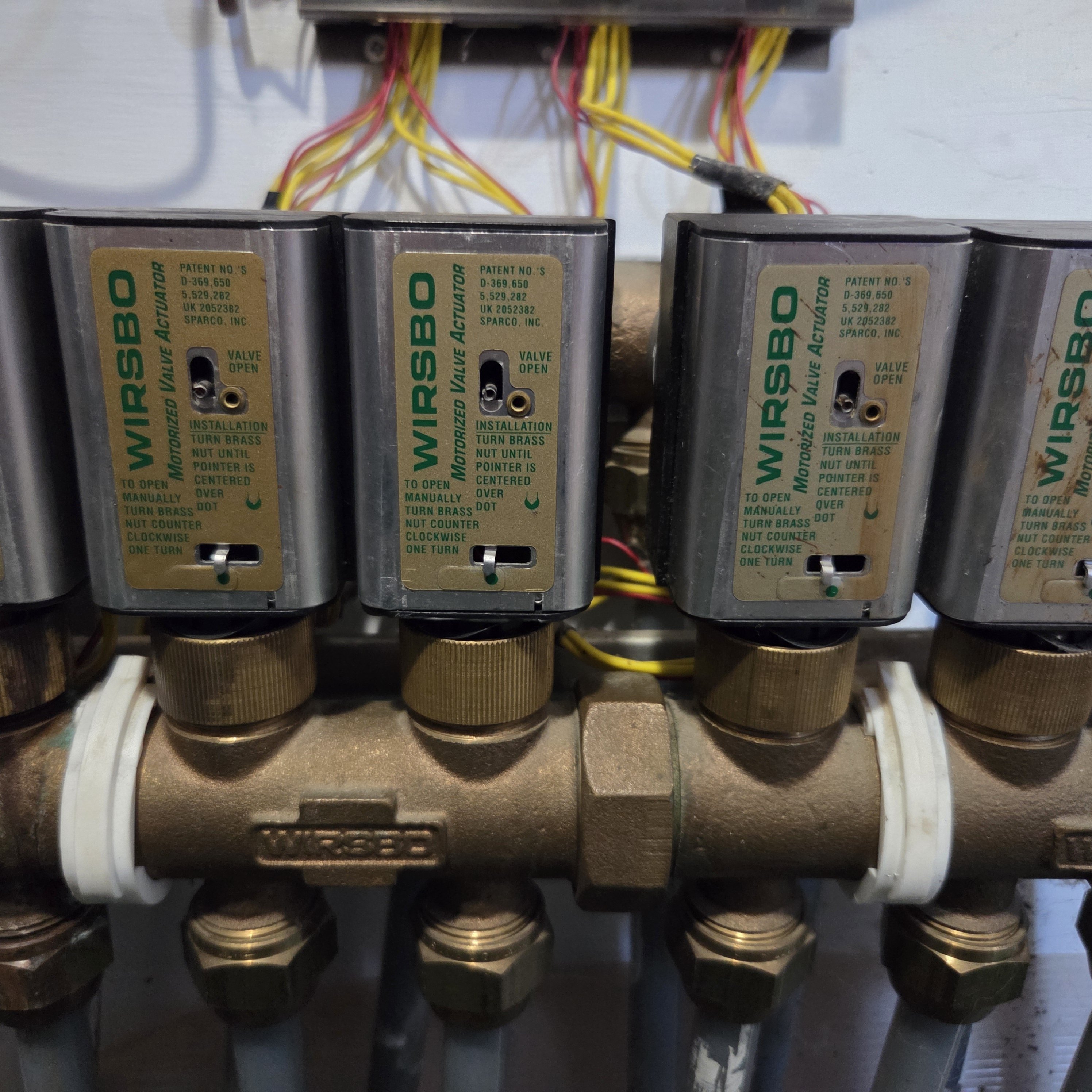
This house has 4 zones and the owner who is an engineer installed a bank of switches in the main hallway to control the individual rooms within each zone. Each switch turns off 1-2 loops depending on the size of the room.


 8.33 lbs./gal. x 60 min./hr. x 20°ΔT = 10,000 BTU's/hour
Two btu per sq ft for degree difference for a slab 1
1 -
Quite the wiring "nest":)
Indicator lights also?
Did you find a work around for those old PowerTrack actuators?Bob "hot rod" Rohr
trainer for Caleffi NA
Living the hydronic dream0 -
No lights. The new Uponor actuators will fit on the old manifolds if you use the specified adapter ring.I think the owners will have me replace the manifolds because of the stuck pin valves. Either the loops don’t heat or they overheat.8.33 lbs./gal. x 60 min./hr. x 20°ΔT = 10,000 BTU's/hour
Two btu per sq ft for degree difference for a slab0 -
The time and energy to rebuild those old manifolds, even if you can find new valves is hardly worth it.
A new manifold with low current draw actuators will save him $$.
Since California is running out of electricity, and all") Bob "hot rod" Rohr
Bob "hot rod" Rohr
trainer for Caleffi NA
Living the hydronic dream 0
0 -
looks like the adjustment tool is built into the black cap on the far right of the manifold. im sure it wont work anymore being plastic and the adjusters being frozen.


 5
5 -
Alan, the black caps on the unused valves is the adjuster for the flow control. Take the cap off and turn it upside down to use it. I will also use a pair of needle nose pliers when I can't find the black cap. I also spray WD-40 of the pins and manually force them up and down a few times to make sure they are loose.
Those valves should also have the indicator pin centered over the green dot when they are powered down. You loosen or tighten the mounting ring to adjust them.
I can't believe they are not all broken yet.
Rick 3
3 -
I can't believe they are not all broken yet.
Agreed.
I had a couple where the plastic frame/shuttle inside broke.
Many where the end switch got carboned up and started chattering my relays ( replacing the internal end-switch on a bunch ).
Finally got tired of doing the switches and started swapping out to thermals.
Thermals are soooo slow, but they just quietly do their job.
FYI, the adapter to make a thermal actuator fit those valves doesnt come with the thermal.. it's a different ring.
30+ yrs in telecom outside plant.
Currently in building maintenance. 1
1 -
Woa, mine chatters and no repair man could figure it out! What do i do to fix!? Show me the way Dave lol.
0 -
@aboczek I should have made a video back then. My memory is not the best, but take off the small cover (tiny screw) , I think thats where the spring rod can be released, then with motor out , can twist metal tabs on the large lid to remove and see the shuttle and the end switch. Cheap switch from Mouser or whatever parts source. Have to drill out rivets and I used wee bolts from a radio controlled cars place to mount the new switch.
The spring is a bit tricky to get back in, but doable. Did a bunch back then.
Adding - I just found an old note on this. The switch for a Wirsbo MVA (or mine anyhow) is a NTE S46 microswitch, and the bolts are 2mm x 15mm
30+ yrs in telecom outside plant.
Currently in building maintenance.1 -
if the flow is backwards they will chatter
Bob "hot rod" Rohr
trainer for Caleffi NA
Living the hydronic dream1 -
Thanks, @Dave Carpentier ! I’ll give it a shot.
Those black adjustable tops on the manifold cartridges. I can’t seem to get a straight answer on how they actually work. When you remove them, they don’t appear to interact with anything inside. When you tighten them down, they seem to either preload the spring in the cartridge or limit the stroke of the pin… or maybe the stroke is limited because it’s preloaded—hard to say!
I guess what I’m asking is: do these disks adjust how far the valve opens when the actuator pushes on the pin to fine-tune flow, or they an option to force the valve some amount to allow a constant trickle of water through the loop? I’ve become more curious because I’m seeing some flow rate issues that seem to be causing my boiler to short cycle. While investigating, I noticed that once the actuators open, they become looser and more wiggly—odd, since you’d expect them to be under more tension. My gut says they’re not properly pushing the pin down and are instead pushing themselves away. The pins aren't stuck and move freely (albeit the springs are strong) Have you come across this before?
0 -
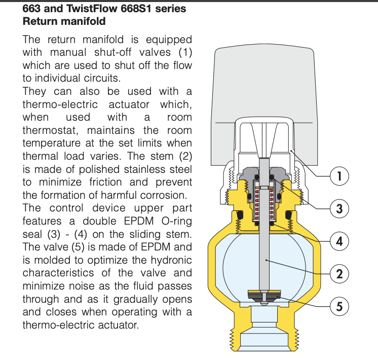
The plastic caps (#1) act as shut-off and flow adjusters. With the cap removed the port is wide open.
Most of those caps have two threads. One threads, the larger one, attaches the assembly onto the manifold. The inner thread allows the cap to move up and down to either regulate, or screwed tightly down it turns that port off. The white cap (#1) in this attachment.
A cut-away shows the pin and shut off operation. This is a Caleffi, most all brands function this way.
The height of that pin is what determines which actuators will work properly. Most are the same manifold attachment thread but the pin (#2) height and pin stroke varies from brand to brand.
There are after-market adapter rings available. In Europe I have seen kits with numerous adapters to interchange actuator brands. We made brass manifolds for Rehau for years, it required an adaptor ring to use their actuators.
A mismatched actuator will usually screw on, but if the stroke is incorrect the valve may always be open a small amount, or not open fully, due to the wrong stroke length.
When you remove a cap and screw an actuator on, it closes the port, as the thermal motor warms the pin (#5) rises up. It lifts the washer #5 off the seat.
 Bob "hot rod" Rohr
trainer for Caleffi NA
Living the hydronic dream0 -
@aboczek If your manifold is like mine , the black cap is just a cover lid / tool. You flip it upside down and then the notch turns the inner part of the valve body up and down. On my supply manifold, I turn the valves up or down to balance the loops. I think the highest one of mine is maybe 2 threads proud, and the lowest is nearly closed (yes, the spring does start to ping while screwing down).
On the return manifold, where the actuators are, I think the valves should be flush with the brass body so that the actuator throw distance is proper.
30+ yrs in telecom outside plant.
Currently in building maintenance.0 -
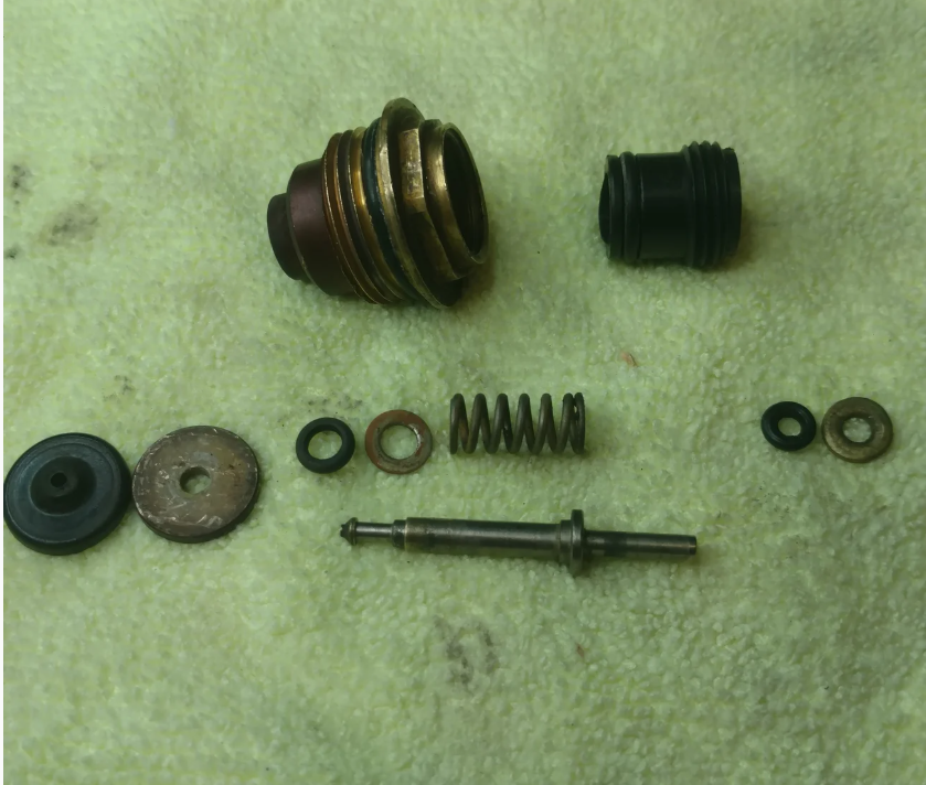
This is what's inside my cartridges (not my photo but exactly the same). The black cap is actually a cylinder that seals against the outer wall and the top of the pin sticks out through the middle. I'm fairly sure it only pushes down on the shelf of the pin and pre loads the spring/adjusts the starting elevation of the pin. The actuators are tightened so the indicators are on the green dots (or near because I'm playing with them) and they are nice and snug. The moment they turn on; the indicators move all the way to the left and they are loose and easily wobbled. Using a laser thermometer on the outgoing loops, I can tell that there is terrible or no flow (temperature is much lower than the outgoing manifold. If I tighten them down until they move water (temperature of the outgoing loop = to the manifold). I do this by turning a little bit at a time and checking the temp and/or pushing down on the whole actuator to see how much space the valve has before bottoming out. When the thermostat is turned back down, the indicators can't return to the green dot and they are way snugger than they were before. At first I thought that maybe they are still retracting and everything is just out of calibration….but when I loosen the brass ring again, I can hear the gears moving so the actuator isn't fully retracted until I loosen the ring. So the big question seems to be: why is it that when they are actuated they lift themselves up and don't push down the pin? The pins move freely and springs typically weaken over time - P.S. Thanks again for listening to me rant and giving advice. It's truly appreciated.
 0
0 -
Same manifold here. The black caps I was talking about are on my supply manifold, like covers over each valve body but you can remove and flip them upside down to use as a tool to adjust the valve height (and thus the flow in that loop)
I still have 2 or 3 of those motorized actuators. The thermal/wax ones are much slower to open/close but I havent noticed an issue in the house on the 4 or 5 that I installed them on.
When you install those MVA and centre the green dot, the valve under it is closed. When it actuates, and its floppy or not opening then possibly the carriage is broken internally in the MVA ? I recall one doing that and some plastic pin or such was broken. It would appear to be open via the little indicator post, but it was wobbly.
30+ yrs in telecom outside plant.
Currently in building maintenance.1 -
Are these the correct parts to switch over to thermal actuators?
Actuator:
Uponor A3023522 Thermal Actuator, Four-Wire - SupplyHouse.com
Adapter Ring:
A3019900 - Uponor (Wirsbo) A3019900 - Spacer Ring VA33 for Thermal Actuators
0 -
Yes
8.33 lbs./gal. x 60 min./hr. x 20°ΔT = 10,000 BTU's/hour
Two btu per sq ft for degree difference for a slab1


Categories
- All Categories
- 87.7K THE MAIN WALL
- 3.3K A-C, Heat Pumps & Refrigeration
- 59 Biomass
- 430 Carbon Monoxide Awareness
- 129 Chimneys & Flues
- 2.2K Domestic Hot Water
- 5.9K Gas Heating
- 122 Geothermal
- 170 Indoor-Air Quality
- 3.8K Oil Heating
- 79 Pipe Deterioration
- 1.1K Plumbing
- 6.6K Radiant Heating
- 396 Solar
- 16K Strictly Steam
- 3.5K Thermostats and Controls
- 56 Water Quality
- 51 Industry Classes
- 51 Job Opportunities
- 17 Recall Announcements