How Forced Air Works
Comments
-
Look guys, I love steam systems and hot water systems much much more than forced air; for all the reasons you guys prefer boilers. But we see a boiler once a month around here, and the rest of the time it's forced air; so why not be the best I can be.0
-
Manual D is spawned from ACCA as I'm sure you know.Steve Minnich0
-
Well, if you disagree then support it with something like: velocity at the blower is no different then 20 feet away from the blower. Don't just say you disagree because a book doesn't support my findings.Stephen Minnich said:
@ProblemSolver - I choose to believe that Manual D does not fall short. I've been doing it that way since I came into this awesome trade a very long time ago. Its ok that we'll just have to agree to disagree.0 -
It's more than a book. That's like saying Manual J is just a book. They are decades old, proven techniques for doing the job the right way, the first time, every time.Steve Minnich0
-
I'm not contesting that the book is wrong; hell, I don't even know what is in that book. You got me over a barrel without a rope, I don't have a leg to stand on, I'm up the creek without a paddle; because I have never read the manual D. But I'm telling you and anyone else interested, what I wrote works like a champ; plus, I gave the scientific explanation for it as-well. So, if you want to disagree, then disagree with the science, the law of physics.0
-
You made me laugh (in a good way) at your opening lines. It's all good. I won't interrupt anymore.Steve Minnich0
-
Might I suggest a read of the link I put up in the beginning of this discussion .
@Stephen Minnich
ACCA did the best they could with the developement of ManJ , S,Tand D . Unfortunately , not unlike our many standards that are coming into question the programs do not support and recognize some BEST PRACTICES . The link i am talking about had some of the most respected names there are in HVAC , john Proctor , Les Lambert , David Butler . These guys can design for any building in any climate for any customer and they can do it right . Very few of them strictly adhere to books or programs written and developed by organizations whose constituency would have to spend more money and make ;less profit . Remember that all the codes and standards are minimum requirements , we can do better , even in forced air .
@ProblemSolver
Don't forget that half the house is supply and the other half is return . The actual home is part of the duct system , the only part that is not sealed . The air handler is no different than a circulator in it's placement in the system . It adds mechanical energy to move air instead of fluid , that's all . If it aint BALANCED it aint right . End of story .
Could you enlighten us about something other than rules of thumb and maybe tell folks how they can DO THE MATH to do it right . Maybe a bit about how to size based on real world Knowledge for when the computer breaks down and there is no electric . Lots of talk about 200 cfm and 700 cfm and 7" holes and 4' holes and using the framing as duct .
if you have a house that is open concept with 1 bedroom and 1 bath , and a finished basement with an open stairwell , how many returns then ?
I guess my point is , this was probably a bad choice for a titleYou didn't get what you didn't pay for and it will never be what you thought it would .
Langans Plumbing & Heating LLC
732-751-1560
Serving most of New Jersey, Eastern Pa .
Consultation, Design & Installation anywhere
Rich McGrath 732-581-38330 -
@Rich - Until somebody rewrites the Manual J book and the computer programs that are Manual J based, I'm sticking with the current version and whatever my experience can add to it.Steve Minnich0
-
I have sized my RA cuts for each run based on location of RA drop and the CFM desired. However I am sure my openings are too large based on your theory. I consider the bottleneck in that run, usually 3 1/2" x 14". If my opening is too large I assume the smallest opening (the floor plate hole) will control the flow. Isn't that what you're doing with the small opening in the RA duct.
Also residential zoning is becoming a big item, only SA is controlled (that I've seen). So what happens with no control on the same RA system?
Panning floor joists and using stud cavities is probably not going away soon. So the real negatives to this are:
Higher friction not being sheetmetal.......but you have a 9 1/2 x 14 wood box, pretty large duct even if it is wood.
Fire hazard.......often the bottom of the joist space is sheetrock, I put 2 x 4 fire stops in the stud space, even above high wall returns.
Mold etc...........these cavities will have conditioned air flowing thru them most of the time.
Not meaning to be critical, just posing questions. Do you feel like a missionary looking for converts on this site.") I don't like it but FAH is here to stay. I have HW boiler and 2 separate zones of ducted AC. Not everyone can afford that here if they are not in the business. Everyone in this area MUST HAVE AC, it wasn't that way 25 years ago, however. No one is allowed to sweat anymore. 0
I don't like it but FAH is here to stay. I have HW boiler and 2 separate zones of ducted AC. Not everyone can afford that here if they are not in the business. Everyone in this area MUST HAVE AC, it wasn't that way 25 years ago, however. No one is allowed to sweat anymore. 0 -
@Rich always good to see you come in on the conversation. Your probably right, bad title. I used it to grab attention so I could share with, whoever, what I had learned 15 years or-so ago. I know it's out of the box info, but it sure works. As for the rest of the system: the near equipment ducts, the supply air trunk and runs, the location of the return air grills and supply air grills, and the room itself; anyone can go to my website to view how I handle those parts. It doesn't go into great detail, but it's enough.0
-
Opps, I didn't add the website. creativecomfort.net0
-
That second paragraph, way too funny.JUGHNE said:I consider the bottleneck in that run, usually 3 1/2" x 14". If my opening is too large I assume the smallest opening (the floor plate hole) will control the flow. Isn't that what you're doing with the small opening in the RA duct.
Not meaning to be critical, just posing questions. Do you feel like a missionary looking for converts on this site.
The first paragraph, I have learned that the stud space will not act as a bottle neck if the hole in the trunk is too large. A lot of that has to do with the square inches in the joist space. Big hole in the trunk line, large space in the joist area; this allows the blower to grab a great amount of air. Then we get to the wall plate, at which the velocity gets increased to try and equal what the joist space and hole in the duct are trying to grab. The only place that can be controlled is at the trunk line.0 -
Sorry, I'll be the first to admit I don't have a clue about this.ProblemSolver said:
this whole thread has been about controlling the air to the room by controlling the air being removed from the room. If you want a cool room in the winter season, then put a magnetic sheet over 70% of the return air grill. Never shut off a supply or return 100%, you will stress out the equipment.ChrisJ said:, give me a way to have thermostats control the airflow to the rooms automatically!
But, I assumed modern equipment could modulate both the burner and blower so I don't see why closing dampers would stress the equipment.
IF that's not true, the equipment still needs improving IMO.
But as you said, this also isn't my thing. If we ever end up in a house with forced hot air it'll be the first thing to go bye bye. I'll haul in some "boat anchors" and put in a proper heating system.Single pipe 392sqft system with an EG-40 rated for 325sqft and it's silent and balanced at all times.
 1
1 -
Dry, lazy and stupid.. as opposed to hydronics being wet, lazy and stupid. Everyone in this thread is missing one of the main reasons that steam and hydronic radiant are SO great. Those two systems are the ONLY systems (other than electric radiant) that can manipulate the mean radiant temperature (MRT) of a given structure. The MRT has more control of human comfort than any other factor known to man kind,
If you want to address comfort, heating AND cooling wise, control and manipulate the MRT.
Forced air got its foot hold during WW2, when materials needed for piping were diverted to the war effort. That and the fact that AC was viable gave them the foothold that they still have today. Contractors look at it as "heating, or cooling", and not a "comfort" system.
And as Rich so correctly pointed out, even if we do a radiant comfort system, moving air is still necessary to provide full spectrum comfort.
While I appreciate Problemsolver's efforts to educate, I am thinking that this is probably not the best forum to be presenting this information. Most of these folks deal with boilers and pipes.
And by the by, radiant cooling IS doable in residential settings. At that point, air movement is limited to addressing the latent energy loads, and the associated energy savings by utilizing hydronic radiant for the majority of the sensible is VERY significant. Commercially, savings of 50% are common.
MRT, and the ability to control MRT is the key to efficient, comfortable design.
ME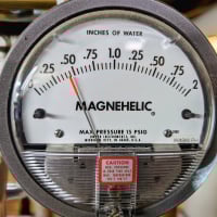
 2
2 -
My dad had his house built in 2006 and it's insulated incredibilly well and as far as I know the forced air system which I begged him to not do, is installed decent as well. All rooms stay decent temperatures all year and his RH is in the 40s without any humidifier which is saying something IMO. Mine is often in the 20s or 30s with a huge humidifier because of how drafty this building is.
That said, even with his VP8000 set to 6 CPH you constantly feel hot/cold/hot/cold/hot/cold the entire time you're there. I have to assume, this is true of any system that uses the air to transfer heat. The system and house are far nicer than what I grew up in which had a 1958 system that would oil can the ducts when it turned on, but its still not a good, proper system IMO.
My drafty 150 year old house with cast iron radiators doing 2 CPH you never feel that. You can't even tell when the boiler is running! Whether it's 30F out, or -8F out it feels the same in here.
I appreciate this thread for what it is, and I know @ProblemSolver isn't trying to convert anyone, he's simply trying to have a discussion regarding something that is often ignored as much as a properly piped steam or hotwater system.
Single pipe 392sqft system with an EG-40 rated for 325sqft and it's silent and balanced at all times.
0 -
And I just realized we're way off base here.
With respect to @ProblemSolver we should probably get back on track to what he was trying to discuss.Single pipe 392sqft system with an EG-40 rated for 325sqft and it's silent and balanced at all times.
0 -
@Stephen Minnich
These are quotes from the beginning of the thread I linked to by David Butler . Question is from a very talented designer who attended an Allison Bailles , HeatSpring course . I know Nathan and he has retrained himself .
Maybe it will make more sense referring to what I said about program constraints and will surely explain why Chris' Dad's home feels the way it does .
Q. Hi all,
I'm in middle of a course on building sciences by a well respected energy expert. He got in to duct design, and said that we have to design duct work with a ESP of .5 IWC and no higher, for energy efficiency and because that's what the blowers are rated @. Now is that possible???
I agree it would be nice if can however my experience says it is almost impossible, the average coil I came across the last five years has a PD of about .25, the default PD for a throw away filter is .1, supply register, return grill, and volume damper, is together .1 (.09). So now am @ .25 + .1+ .1 = .45 IWC before I start with the actual duct work.....
A. It matters whether we're talking furnaces or air handlers since the coil is external with a furnace but internal with an air handler. I routinely specify a maximum of 0.30 to 0.40 IWC TESP for air handlers.
The 0.5 IWC design max for furnaces is not just for efficiency but for many furnaces, that's the maximum available static. So you'd rather be *below* a half-inch. When 2006 efficiency standards went into effect, some manufacturers resorted to under-sizing furnace blower motors. So if you don't pay attention to every contributor to static loss, you'll end up with inadequate airflow in cooling mode. Happens all the time.
For example, when specifying furnace+AC, you have lots of coils to choose from. Check the static loss tables and use the the largest and least restrictive coil that satisfies the latent load. Fortunately, with homes getting tighter, latent loads are much lower so we can get away with a larger coil surface area. The important thing is "design and measure, don't guess".
You can reduce filter static drop by increasing filter surface area. My rule of thumb is no more than 200 FPM face velocity (less for ducted mini-splits). On systems with a horizontal blower and ceiling return (typical in an encapsulated attic), I specify filter grilles since I can make it whatever size I need. Of course, the return duct must be tight to prevent filter bypass.
Whenever possible, I prefer to use a vertical blower (typical in finished basement with mechanical room), in which case I go with a ductless return, with filter(s) mounted on side(s) of the return plenum riser. I use transfer grilles, jump ducts and/or door undercuts to ensure a low static return path from every room. This strategy not only reduces ESP but improves air circulation and simplifies duct routing through tight floor systems. Moreover, in a zoned system that supplies multiple floors, a ductless return ensures good air mixing between floors. This is especially important below-grade as it helps keep RH under control in summer when there's little sensible. Closing off a finished basement is a bad idea (think dank, musty).
A. part2
"Also keep in mind that the Manual D Appendix 3 equivalent length values are based on 900 FPM. There's no reason to run that high, especially through branch fittings. The EL's (and static losses) obviously go down when you up-size ducts for a lower velocity. There's a simple but often ignored formula in Section A3-3 to convert nominal EL's to other velocities. Also, I highly recommend Appendix 4 (Fitting Equivalent Length Adjustments).
I don't know about Elite Ductsize but I don't think Wrightsoft Right-D makes this conversion, which would mean it overstates static losses when you design to a lower velocity than 900 FPM. I no longer license Right-D so this is based on testing done by a colleague several months ago.
As a designer, I get a lot of push-back from contractors about low velocity. Here's the thing.. in low-load homes, it's damn near impossible to satisfy "old school" velocity and diffuser throw rules-of-thumb when your design airflow works out to 0.25 CFM per square foot or even less. So what to do?
What folks don't realize is the more efficient the shell, the less important velocity and register throws become. I participated in the last Manual D Review Committee (3rd Edition) with the sole purpose of making sure this issue was addressed. The result of my efforts was modest -- Hank added the following guidance in his typical deadpan style...
Appendix 15 Air Velocity for Ducts and Grilles, Section A15-5 Conclusion:
"There are scores of things to worry about when designing and installing a comfort system. Low velocity through a duct airway is not one of them. "
Pretty interesting stuff guys . for those who might ask , Ok , who the hell is this David Butler / , Robert Bean and David have collaborated on a few projects , if Bean does that you can bet this guy is GOOD .
I urge everyone whom is actually interested and still believes there are things to learn to read this discussion and some of the reference materials linked . These guys are the real deal and know how to perform in the newer , tighter homes . There is room for this discussion here , this is after all , HeatingHelp .
Problem Solver , My family has been doing this for a hundred years , I have discussed some of the things we have learned with my uncles who are still on the right side of the lawn and they are astounded , except for one who knew this stuff all along and nobody would listen to him either . Imagine guaranteeing less than a 1/2* temp difference from room to room back in 1970 , because that's exactly what he did with baseboard .You didn't get what you didn't pay for and it will never be what you thought it would .
Langans Plumbing & Heating LLC
732-751-1560
Serving most of New Jersey, Eastern Pa .
Consultation, Design & Installation anywhere
Rich McGrath 732-581-38330 -
I appreciate the efforts, Rich, in terms of improving on the ACCA's Manuals that are currently in place. And as soon as formal training is available on those upgrades I'll be front row and center but until then I have to keep moving forward with what's already in place and (more than) generally accepted. I wear enough hats as it is and, quite frankly, I'm not even close to smart enough to rewrite those books.Steve Minnich

 2
2 -
It never dawned on me to mention it; I too am a 3rd generation HVAC tech. Grandpa, my father, and now me - no uncles though. Back in the day when graduated supply ducts were being installed; most of them got sized wrong - the fabricator would add 3 1/4" per supply. I worked with a man - and his father designed them by adding 2" per supply, with the same results you are talking about - 1/2* diff. back in the 50's & 60's. This man never mentioned anything about what his father did with the R/A.Rich said:
Problem Solver , My family has been doing this for a hundred years , I have discussed some of the things we have learned with my uncles who are still on the right side of the lawn and they are astounded , except for one who knew this stuff all along and nobody would listen to him either . Imagine guaranteeing less than a 1/2* temp difference from room to room back in 1970 , because that's exactly what he did with baseboard .0 -
If what you are saying is fact I have a question for everyone installing forced air . What happened to that knowledge because it certainly does not exist today ?
Everyone readily admits to the superior comfort of hydronic heat including @ProblemSolver . just goes to show that Tair in a room is not a proxy for thermal comfort . i can just picture the dedication of a man or men 50+ years ago walking a home with a thermometer in hand to verify room temps from room to room .You didn't get what you didn't pay for and it will never be what you thought it would .
Langans Plumbing & Heating LLC
732-751-1560
Serving most of New Jersey, Eastern Pa .
Consultation, Design & Installation anywhere
Rich McGrath 732-581-38330 -
I don't understand how anyone can see my theory as something that can't be true. Steam travels the same way - "high pressure goes to low pressure (every time), but with steam it happens in the radiators; and with forced air it happens in the rooms - other than that, there is no difference.0
-
Did someone say something that questions your theory ? I did not see it . We all know how forced air works , I am waiting for the magic bullet that deals with proper duct design , external static pressures , and how to do it right . It can be done and be rather comfortable , how to do that is what has been lost over the decades .
How do you determine the velocities and ESP and the like . Simple fact is that the way equipment id now designed it is almost impossible to get the contractor to size the ducting right . Why would anyone use ducts that are larger than the outlet of the equipment they are installing ? It's too expensive and they cannot compete . Yet that is what must be done to get a forced air system to perform in what many of us would consider an acceptable manner and provide comfort and not just heat . Will forced air even have a place in the houses and buildings that are coming down the pike ? They will be tight , have heat losses of around 10,000 BTUh @ design for a 2,300 sf house and probably only need to move <400 CFM . I guess forced air guys better start reading the book that goes with Manj and the others because the program does not now recognize or reconcile anything anywhere near that low . Forced air is alot more like hydronics than most know and dependency on programs that do not recognize real world conditions are the reason that industry suffers much like the hydronic industry . At least hydronics has the capability of not moving air past people and robbing their natural heat .
Please continue , I am listening although others may not be .You didn't get what you didn't pay for and it will never be what you thought it would .
Langans Plumbing & Heating LLC
732-751-1560
Serving most of New Jersey, Eastern Pa .
Consultation, Design & Installation anywhere
Rich McGrath 732-581-38330 -
Steam is a bad example, but overall I agree.ProblemSolver said:I don't understand how anyone can see my theory as something that can't be true. Steam travels the same way - "high pressure goes to low pressure (every time), but with steam it happens in the radiators; and with forced air it happens in the rooms - other than that, there is no difference.
Steam also has the ability to condense and pull more steam into the area. I believe this is the entire reason my system can operate at such a low pressure but I'm guessing and have nothing to back this up.
But, I agree with Rich, no one is doubting your theory that I know of. I'm certainly not.Single pipe 392sqft system with an EG-40 rated for 325sqft and it's silent and balanced at all times.
 1
1 -
First, it’s important to know, the code around here is; there must be a return grill in every room except for the kitchen and bathrooms. Because of this, we typically end up with 2 more return grills than what the system requires. And because we normally shoot for approximately 200 CFM’s per return grill, we have to spread out the difference and reduce the CFM’s to 100 for a couple of the grills. Here’s an example: A 2,800 sq. ft. 2 story home; 3 bedrooms and a bath on the second floor; and a family room, dining nook, formal dining room, living room, and an office on the first floor. That’s eight rooms that must have return grills in them; but the family room is large so it requires a double return with 3 supplies and a fourth supply at the front door, which gives us a total of 9 returns. This house is well insulated with R33 in the attic, and 2x6 outside walls with R19. The house is well shadowed on its south side by large oak trees, so we will use a SEER 16, 3 1/2 ton, cooling system. That’s 1,400 CFM’s, but we have 9 returns at 200 CFM’s per return - equaling 1,800 CFM’s. So now our goal is to reduce some of the returns down to 100 CFM’s to match the 1,400 CFM’s we are shooting for. Let’s say that the first floor has 11 S/A runs and the second floor has 5 S/A runs. That’s a total of 16 S/A runs, but there are 3 small rooms on the first floor (office, 1/2 bath, & dining nook), they don’t need 6” pipe runs to them to heat them. The office and dining nook only need 5” runs and the 1/2 bath only needs a 4” run. Now it’s time to balance the return: we automatically shoot for 200 CFM’s at all second floor returns because they are furthest away from the blower, our holes in the trunk will be between 8” & 10” as to offer the blower absolutely no resistance at all. The office, dining nook, and one of the living room returns will get a 4” or 5” hole in the trunk to restrict the blower to a 100 CFM draw. Leaving the remainder returns to a 5” or 6” hole in the trunk to restrict the blower to about 150 to 200 CFM’s. Of course, all this is based off the location of each return in conjunction to the distance from the blower. In a matter of speaking, this is how I balance my return.0
-
Placement of the return grill and supply register/s in a room is also important. The idea here is to, what I like to call, “wash the room”. Placement of the return air grill should almost always be near that room’s entry door, on an inside wall. Next, every supply register has what is called a throw pattern. Most 4 x 10 floor registers (located at an outside wall) will throw the air seven feet up diagonally in opposite directions; much like an oriental hand fan. The newly conditioned air coming into the room will begin to move towards the return grill; so placement of the supply register should be considered by how it can best “wash the room” as it moves towards the return grill.0
-
@Stephen Minnich didn't so much question it, he believes that if it's not in a book than there cannot be any merit to it. So, that was for him and any others that have a hard time with change.Rich said:Did someone say something that questions your theory ? I did not see it .
0 -
This part has such a great influence on the equipment’s performance. I like to compare it to the “near boiler piping” of a steam boiler. The near boiler piping is part of the boiler and not so much part of the rest of the system. The “near furnace” duct work is part of the furnace and not so much part of the trunk lines/system.
This discussion will be about a furnace in the basement, therefore it’s an upflow furnace. Today’s furnaces are 33 inches tall; why? I have asked 3 manufactures supply houses this question, and they all answered the same; to get the furnaces stacked three high in a semi-truck trailer. Does that sound familiar @DanHolohan ? Hot water boilers shipped with the circulator mounted on the return pipe. Well anyways; when they reduced the height to 33 inches, they had to reduce the space in the blower compartment as-well, and now the blower has less space to get the air it needs. So now, every furnace I install gets mounted on a 3” to 5” tall return base, and my filter cabinet (20x25x5) will get a minimum of a 3 inch “stand-off” between the furnace and filter cabinet. This “stand-off” is mounted to both the return base and the side of the furnace. And yes, it all gets sealed. This allows the opposite side of the blower (from where the return ties in) to draw air without it having to work hard for it. With both sides of the blower drawing the air it needs, without having to work hard for it, we have a better chance of getting our trunk line design to work.
This next part I like to start as a question; what is the purpose of the return air drop? When I see all the other installs out there in my area, and how they size the return air drop; it gets me to believe that everyone thinks the return air drop is part of the return air trunk. IT IS NOT!! The only purpose of the return air drop is to tie the return trunk line into the blower - period... Therefore, it's a connector, and not a part of the return trunk line. Therefore, its’ size should never cause resistance on the blower. The resistance on the return side of the blower should always begin in the return trunk. So, if the return trunk at the furnace is an 8 x 24 duct, then return drop must be a 10 x 24, so-as-not-to cause any resistance on the blower. As a rule of mine, I rarely use a return drop smaller than 10 x 24.
Think about not doing all this! - Size the return drop the same as the return trunk. Mount the filter cabinet up against the side of the furnace without the return air base. The cut-out on the side of the furnace is 14 inches tall with about 1 1/4 inches of metal left at the bottom. That’s 15 ¼ inches off the floor; but the filter is 20 inches tall. So there is a 5x25 inch space of the filter not being utilized. Plus, putting the filter that close to the blower further chokes the blowers’ ability to pull the air it needs. This is the reason why heating contractors tell their customers that the furnace only has a 15 to 20 year life cycle. And in this case they are right. This kind of work puts undue stress on the furnace and shortens its’ life because the furnace will never see the volume of air flowing through it, that it was designed for; but the furnace will continue to try, up to the day it dies.0 -
Got a photo or a sketch of this? Near-zero sheet metal experience here but I'm interested in learning how we might improve things for the furnace customers.ProblemSolver said:every furnace I install gets mounted on a 3” to 5” tall return base, and my filter cabinet (20x25x5) will get a minimum of a 3 inch “stand-off” between the furnace and filter cabinet. This “stand-off” is mounted to both the return base and the side of the furnace. And yes, it all gets sealed. This allows the opposite side of the blower (from where the return ties in) to draw air without it having to work hard for it. With both sides of the blower drawing the air it needs, without having to work hard for it, we have a better chance of getting our trunk line design to work.
0 -
Wanna improve things Kurt ? Call David . If you have the time to spare , LMFAOYou didn't get what you didn't pay for and it will never be what you thought it would .
Langans Plumbing & Heating LLC
732-751-1560
Serving most of New Jersey, Eastern Pa .
Consultation, Design & Installation anywhere
Rich McGrath 732-581-38331 -
Not sure if this is relevant to this discussion but I see some 1950's & early 60's houses set up with the return on exterior perimeter and supplies mostly high wall with wall stack ducting. An "old guy" told me that with the supply at 7' that was the ideal situation for comfort. I always assumed this was a left over from the gravity air "octopus" systems where you wanted the maximum temp difference to induct gravity air flow. But this design has fallen from favor, seemly for good reason. Or was there any "method to the madness"?
Whenever I change one of these out I use the old supplies for returns, usually add more and cut in floor regs on the perimeter.0 -
I just helped a friend with a house set up like this . He bought the equipment and I changed out the indoor unit and did the sheet metal work. In the past when I did residential work for a living we would convert these to supply to the exterior walls , but I wasn't going to do all of that now. He has lived with it all summer and says that he is extremely happy with the performance and the cost to operate. From what I was taught years ago this system shouldn't work at all ducted like this , we had plenty of " degree days " here this summer that blow that logic to heck.JUGHNE said:Not sure if this is relevant to this discussion but I see some 1950's & early 60's houses set up with the return on exterior perimeter and supplies mostly high wall with wall stack ducting. An "old guy" told me that with the supply at 7' that was the ideal situation for comfort. I always assumed this was a left over from the gravity air "octopus" systems where you wanted the maximum temp difference to induct gravity air flow. But this design has fallen from favor, seemly for good reason. Or was there any "method to the madness"?
Whenever I change one of these out I use the old supplies for returns, usually add more and cut in floor regs on the perimeter.
hvacfreak
Mechanical Enthusiast
Burnham MST 396 , 60 oz gauge , Tigerloop , Firomatic Check Valve , Mcdonnell Miller 67 lwco , Danfoss RA2k TRV'sEasyio FG20 Controller
0 -
The 1958 house I grew up in which still had it's original furnace when we moved out in 2006 had all of the supplies on exterior walls about a foot off the floor or so. Small rooms had one supply, large ones had two. There were three returns, a huge one in the hallway, a small one in the master bedroom and a small one in the livingroom. All were low down same as the supplies.
Single pipe 392sqft system with an EG-40 rated for 325sqft and it's silent and balanced at all times.
0 -
Having designed and installed systems with an ESP of .35 and otherwise below .5, my logic and experience would indicate that @ProblemSolver is 100% correct in his methods.
With the current equipment selection options and the blower capabilities, we are stuck with putting in a very large duct system. With such a large duct system, it essentially becomes depressurized and you loose control of the air flow in your supply duct system. At this point the air in the supply, sees the pressure in each respective room and will go to the lowest pressure. The lowest room pressure, is of course created by the return duct system. Therefore, our system becomes balanced on the return. There is more than one way to do it. Problem solver indicated he likes to balance his return with return branch sizing at the trunk. I personally like using filter grills to keep the duct system clean and allow ample surface area for higher Merv filters. You cannot get the surface area needed at the equipment location for anything other than a fiberglass filter. I size the grills at a max of 300 FPM face velocity, (depends on filter type) and use that to balance the system. The grills are sized according to how much air is to be drawn from that area and strategically placed to wash the room of air.
A system like this is so quiet, the only thing you hear is the filters settling in place when the blower turns on.
And Hydronic heating is still way better. I guarantee it! 3
3 -
What about the high velocity systems? I can only imagine they would over pressurize the house. I've only worked on a few of them. Never designed or installed one0
-
Other factors that would be considered.
Superheat for your compressor?
Too much temperature rise across furnace?
Yay or nah?0 -
A properly designed forced air system BEGINS with a room by room load calculation. The amount of cfm per room is based on the btu load of that room and you size the duct accordingly. If you do it properly the first time, you'll match the return cfm to the supply cfm for each room. Unfortunately, with forced air the duct is serving two entirely different needs -cooling and heating. In a perfect world, you'd have two different size ducts for each.
IF the trunkline is sized properly and the size of it is reduced properly as it goes, you'll maintain static pressure and velocity pressure throughout.
The smaller opening on the side of 33" tall furnaces was never meant to be the size of the return air filter. It says so in every Installation manual I've ever read. You need to do the math. If you have a blower delivering 1400 cfm - you need to determine the pressure drop of the filter you're going to use @300 fpm(velocity).
CFM/Velocity = Filter area in square feet
1400/300 = 4.67 sf filter area
Make a change fitting to accommodate the correct filter size.
*If you're @ 2000 CFM, you'll need a bottom return.
And when you look at the data plate of a furnace, the .5 ESP they list there is not something you're necessarily going to see in the field. It just means that's the pressure the blower's rated cfm has been tested at. In the field, your ESP may be .79. If you need 1200 cfm and you measure .79 ESP with a manehelic gauge, you need to be able to read the manufacturer's blower tables to see if that blower is capable of delivering 1200cfm @.79 ESP. You really can't diagnose static pressure problems in forced air system without knowing how to use a magnehelic gauge or how to read and understand the data the manufacturer is freely given you.
Steve Minnich0 -
@njtommy - I think I'm in the minority on high velocity too. If properly designed and installed, they shine and are as quiet as any other forced air systemSteve Minnich0
-
So it's like sleep in a wind tunnel? Lol0
-
It's not hydronic heat quiet, not even close.
Steve Minnich0 -
@Harvey Ramer sounds like we need zone valves on returns for HVAC...hmmmmLANGAN'S PLUMBING & HEATING LLC
Considerate People, Considerate Service, Consider It Done!
732-751-1560
email: langansph@yahoo.com
www.langansplumbing.com0


Categories
- All Categories
- 87.6K THE MAIN WALL
- 3.3K A-C, Heat Pumps & Refrigeration
- 59 Biomass
- 430 Carbon Monoxide Awareness
- 124 Chimneys & Flues
- 2.2K Domestic Hot Water
- 5.9K Gas Heating
- 120 Geothermal
- 169 Indoor-Air Quality
- 3.8K Oil Heating
- 78 Pipe Deterioration
- 1K Plumbing
- 6.6K Radiant Heating
- 396 Solar
- 16K Strictly Steam
- 3.5K Thermostats and Controls
- 56 Water Quality
- 51 Industry Classes
- 51 Job Opportunities
- 18 Recall Announcements