Welcome! Here are the website rules, as well as some tips for using this forum.
Need to contact us? Visit https://heatinghelp.com/contact-us/.
Click here to Find a Contractor in your area.
If our community has helped you, please consider making a contribution to support this website. Thanks!
stumped and need your help .....
Options

jpf321
Member Posts: 1,568
OK guys .. I've got a toughy ... image attached below ..
Cousin of mine complains that he has banging in the morning ....
so they let out some water .. banging quiets
next cycle (or at least very soon) .. boiler overfilled ..
remove some water bring back to NWL (28.5")..
next cycle (or at least very soon) ... empty ..
add some water to NWL ..
next cycle .. overfilled ..
remove some water to NWL ..
next cycle empty ..
etc ...
manual water feed. no leaks.
aha .. but he rerouted his original return to make way for 2 doorways ... finished basement.
I'm having a really hard time visualizing what is happening every other
cycle that both hides water AND overfills .. could someone explain it to
me .. i'm just not seeing it.
he had NO vents on the mains ..
a plug in the original vent location "vent 1" ..
I suggested he add vents to both original location and new 2nd location "vent 2" to attempt to un-airlock the long sloping return from vent1 to vent 2 ..
he did .. added a Gorton #1 at each location ..
NOW... Gortons don't seal on water and so ..
vent 1 is raised as high as possible .. it pees water at end of cycle ..
vent 2 is raised higher than NWL .. it pees water at end of cycle ..
+ Would swapping with Hoffman 75's instead of G1s help at all?
+ Are vents even needed to get water back to boiler and maintain cycle-cycle water content? I know a false water line needs a vent.
+ should I have 1 vent or 2 vents as currently exists? which one to keep?
+ what other types of vents seal on presence of water?
i know the BIG ANSWER is to drop the return below NWL and make it fully wet beginning before Vent 1 location after from the bottom of his "U" .. but this is going to involve significant deconstruction of his finish work.
i know he should have never rerouted the pipes to make way for the doors ..
i adjusted his p-trol down to 1.5 "Honeywell" PSI. Would running at even lower pressure (vaporstat) help to alleviate his woes?
I don't have exact measurements of everything except the NWL .. I can get em tomorrow. I know we need Dim A to be 28" above NWL .. and that with his U the way it is .. the FALSE WL is probably the horizontal between "vent 1" and "U" .. this I surmise is the biggest problem ..
by why would vent 1 be peeing if it is raised HIGH?
it's a WeilMcClain ~265sq ft boiler and he has a 1" return along the very long slope between V1 and V2 .. is the return too small .. again .. break up of finish work to correct .. I didn't find the manual yet, nor do I know what the WM return tapping is on this boiler...
he ran the U in copper .. I don't know what size ..
as far as I know .. there are no heat complaints upstairs and all rads presumably heat.
he has a HW loop running in the basement pulling from the bottom of hartford..returning to the top of "a tankless plate" in boiler front ... but running the loop-pump did not seem to affect the NWL so I eliminated it from the equation.
THANKS!!!
<img src="http://content.screencast.com/users/JPF321/folders/Jing/media/7762525f-6a09-4c2c-be92-154d881f0413/2011-12-15_0106.png" width="948" height="565" alt="" />
1-pipe Homeowner - Queens, NYC
NEW: SlantFin Intrepid TR-30 + Tankless + Riello 40-F5 @ 0.85gph | OLD: Fitzgibbons 402 boiler + Beckett "SR" Oil Gun @ 1.75gph
installed: 0-20oz/si gauge | vaporstat | hour-meter | gortons on all rads | 1pc G#2 + 1pc G#1 on each of 2 mains
Connected EDR load: 371 sf venting load: 2.95cfm vent capacity: 4.62cfm
my NEW system pics | my OLD system pics
0
Comments
-
RE
Is the drawing of the boiler accurate? Is there an equalizer?
The piping change is a problem. You've now made your A Dimension the height between the end of the steam main and the top of the raised U.
It would be fine to go under the door, but then keep it a wet return from that point on.
Also, the first vent is not doing anything where it is. It's should be located before the drop under the door. That's also why it's leaking. It's being flooded by water.0 -
i think its now a piping nightmare.
I think he is going to have to drop the return below the boiler water line, leaving adequate 'a' dimension to stack water, or drop to a condensate tank and pump it back over to the boiler.gwgillplumbingandheating.com
Serving Cleveland's eastern suburbs from Cleveland Heights down to Cuyahoga Falls.0 -
Help venting, draining:
I;m not a Steamer.
Think like I do. I drain a lot of houses for the winter. How would you get the water out of that "loop" or TRAP. In spite of what I heard someone once said, that water doesn't care where it goes, Steam does. It won't go where water is unless it can EASILY push it out of the way.
If it worked before the pipe change, and now it doesn't, the problem is usually in the change. If I was draining the system. I could blow the water out of that wet leg with compressed air. Steam doesn't have the "pressure" to do that.
It's like an old time carpenter once told me about house leaks that leaked in the wind.
"The water won't go where the wind can't blow". If you have an air leak in your house, and the pressure inside is lower than the outside, the wind will carry the water in with it when it blows.
Time for some changes.0 -
A possible cure
JP, The best option you have already identified is lowering the pipe to below the water line at the point it drops for the door. But, there may be another option that works. I'm not sure why the vents are peeing without beaing able to check pressures at the time, but that big dip creates a huge trap and nothing will work correctly because of it.
I am attaching a diagram of piping around an obstruction. The obstruction shown is a beam, but I don't see why it work for a larger obstruction such as the door in your case. The bottom image is for the steam main.
This may be a lot easier than tearing the walls apart to lower the rest of the piping, and it may work.Dave in Quad Cities, America
Weil-McLain 680 with Riello 2-stage burner, December 2012. Firing rate=375MBH Low, 690MBH Hi.
System = Early Dunham 2-pipe Vacuo-Vapor (inlet and outlet both at bottom of radiators) Traps are Dunham #2 rebuilt w. Barnes-Jones Cage Units, Dunham-Bush 1E, Mepco 1E, and Armstrong TS-2. All valves haveTunstall orifices sized at 8 oz.
Current connected load EDR= 1,259 sq ft, Original system EDR = 2,100 sq ft Vaporstat, 13 oz cutout, 4 oz cutin - Temp. control Tekmar 279.
http://grandviewdavenport.com0 -
vents...
there is an equalizer .. i neglected to draw it late last night .. my apologies.
were placed to try to break airlock/vacuum for return water. they were not intended to vent for steam, I knew there was a water seal and that steam would never reach them.1-pipe Homeowner - Queens, NYC
NEW: SlantFin Intrepid TR-30 + Tankless + Riello 40-F5 @ 0.85gph | OLD: Fitzgibbons 402 boiler + Beckett "SR" Oil Gun @ 1.75gph
installed: 0-20oz/si gauge | vaporstat | hour-meter | gortons on all rads | 1pc G#2 + 1pc G#1 on each of 2 mains
Connected EDR load: 371 sf venting load: 2.95cfm vent capacity: 4.62cfm
my NEW system pics | my OLD system pics0 -
agreed....
o hadn't considered a pump .. do they make a small residential cond. pump. that can handle the temps of the condensate? i probably wouldn't recommend a pump as that is much more maintenance .. but thanks for the idea.1-pipe Homeowner - Queens, NYC
NEW: SlantFin Intrepid TR-30 + Tankless + Riello 40-F5 @ 0.85gph | OLD: Fitzgibbons 402 boiler + Beckett "SR" Oil Gun @ 1.75gph
installed: 0-20oz/si gauge | vaporstat | hour-meter | gortons on all rads | 1pc G#2 + 1pc G#1 on each of 2 mains
Connected EDR load: 371 sf venting load: 2.95cfm vent capacity: 4.62cfm
my NEW system pics | my OLD system pics0 -
Both vents are in the wrong place
Vent 1 is after the loop seal your friend installed, so no air can reach it.
Vent 2 looks like it's close to the boiler's waterline, so not only can the air not reach it, but it's in the active range of the "B" dimension. Yes, it's a "B" dimension now, not an "A" dimension- the loop seal blocks the leftover steam pressure. So the vent is being flooded every time the boiler runs.
Vent 1 might be getting flooded for this reason too, but it's hard to tell from the diagram.Baltimore, MD, USA
Steam, Vapor & Hot-Water Heating Specialists
Oil & Gas Burner Service
Consulting0 -
this is the 2nd ....
suggestion for this type of bypass ... but your's is with a picture!
please note that there are NO risers past the U-trap so I don't really have to worry about getting steam past the U .. but I think this may work simply to equalize the pressures on both sides of the U.
water will then back up the long sloping return back to the boiler and will now have steam pressure behind it to keep it flowing back to the boiler ..
whereas currently the steam pressure behind the water must be used to push the water up the U-trap .. and once the pressure goes away the trap drops back down, perhaps pulling water OUT of the boiler..although with the vents now in place, the vacuum should be broken. there should be definitely enough Dim A. along the long sloping return back to boiler for water to stack .. maybe we can get away with 1/2" or 3/4" bypass just to move the steam (pressure) across the top. and it becomes a non-draining drip.
however, I'm going to have a hard time convincing my cousin to put in a horizontal upper bypass for the steam.1-pipe Homeowner - Queens, NYC
NEW: SlantFin Intrepid TR-30 + Tankless + Riello 40-F5 @ 0.85gph | OLD: Fitzgibbons 402 boiler + Beckett "SR" Oil Gun @ 1.75gph
installed: 0-20oz/si gauge | vaporstat | hour-meter | gortons on all rads | 1pc G#2 + 1pc G#1 on each of 2 mains
Connected EDR load: 371 sf venting load: 2.95cfm vent capacity: 4.62cfm
my NEW system pics | my OLD system pics0 -
thanks ..
as mentioned above .. i knew that steam/air would not be reaching vent 1 .. but i was trying to break airlock/vacuum .. i will read up on Dim B. so I am clear about what you are describing. there is possibility to raise vent 2 higher .. but let me read up a bit more.
i think I'm also going to tell him to invest in a vaporstat and get the pressures much further down.1-pipe Homeowner - Queens, NYC
NEW: SlantFin Intrepid TR-30 + Tankless + Riello 40-F5 @ 0.85gph | OLD: Fitzgibbons 402 boiler + Beckett "SR" Oil Gun @ 1.75gph
installed: 0-20oz/si gauge | vaporstat | hour-meter | gortons on all rads | 1pc G#2 + 1pc G#1 on each of 2 mains
Connected EDR load: 371 sf venting load: 2.95cfm vent capacity: 4.62cfm
my NEW system pics | my OLD system pics0 -
condensate loops
These condensate loops have been in operation since 1934. The loop approach is shown in the instructive books sold on this site.0 -
all fixed ...
I was over there tonight, just got back ....
+ We cleaned out his #67 .. it was full of crud. Now it ain't
+ I gave him the vaporstat from my boiler and cranked the pressure down to 6oz. vs. a normal 404A of god knows what PSI.
+ I installed a clear-tube manometer in the position of vent #2 and found that at peak, the water gets up to about 20" with the vaporstat set @ 6oz .. he had previously had it on an 18" nipple with the 404A ..
+ We reinstalled vent #2 on a 36" nipple since we knew that 20" was the max we saw it attain.
+ We ran several 6oz cycles and the water line stayed steady.
+ We feel very confident that the water was making it back to the boiler and that vent #2 would no longer pee.
+ When he gets back from 3weeks abroad, we will likely add a vent in the corner diagonally across from boiler to assist in speeding the steam down the main, he found an old plug in that corner and that is exactly what is needed since vent1 position is sealed by the water loop. So we need venting in corner before the U-trap.
thanks for everyone's input. If anything changes, I will let you know ..
I found the answers one pages 32-34 of TLAOSH where the solution, as is common, is "CRANK IT DOWN". thanks dan!1-pipe Homeowner - Queens, NYC
NEW: SlantFin Intrepid TR-30 + Tankless + Riello 40-F5 @ 0.85gph | OLD: Fitzgibbons 402 boiler + Beckett "SR" Oil Gun @ 1.75gph
installed: 0-20oz/si gauge | vaporstat | hour-meter | gortons on all rads | 1pc G#2 + 1pc G#1 on each of 2 mains
Connected EDR load: 371 sf venting load: 2.95cfm vent capacity: 4.62cfm
my NEW system pics | my OLD system pics0 -
thanks .. was
there an image that accompanied your post? it didn't show up.. I have all of Dan's books .. do you have a page reference?1-pipe Homeowner - Queens, NYC
NEW: SlantFin Intrepid TR-30 + Tankless + Riello 40-F5 @ 0.85gph | OLD: Fitzgibbons 402 boiler + Beckett "SR" Oil Gun @ 1.75gph
installed: 0-20oz/si gauge | vaporstat | hour-meter | gortons on all rads | 1pc G#2 + 1pc G#1 on each of 2 mains
Connected EDR load: 371 sf venting load: 2.95cfm vent capacity: 4.62cfm
my NEW system pics | my OLD system pics0 -
Excellent Report!
JP, glad to hear you got it worked out.
I agree completely with adding the new vent just before the drop for the doorway. That will improve performance. Also, I would make sure that the vent at location number 1 stays in place. You didn't indicate that you were going to remove it, but I'm adding the word of caution.
Since the is no steam/air loop going up over the door, the section after the drop will not be able to breath. I cannot see what the actual configuration of the piping is, but there is a very remote chance that a syphon could occur under certain conditions and draw all of the water out of the drop portion of the loop. Retaining the vent at location 1 will prevent that from occuring as it will serve as a vacuum break.
Tell your cousin that next time he should talk to you "before" he does any work on his steam system.Dave in Quad Cities, America
Weil-McLain 680 with Riello 2-stage burner, December 2012. Firing rate=375MBH Low, 690MBH Hi.
System = Early Dunham 2-pipe Vacuo-Vapor (inlet and outlet both at bottom of radiators) Traps are Dunham #2 rebuilt w. Barnes-Jones Cage Units, Dunham-Bush 1E, Mepco 1E, and Armstrong TS-2. All valves haveTunstall orifices sized at 8 oz.
Current connected load EDR= 1,259 sq ft, Original system EDR = 2,100 sq ft Vaporstat, 13 oz cutout, 4 oz cutin - Temp. control Tekmar 279.
http://grandviewdavenport.com0 -
thanks....
the vent location of vent2 stayed in place .. vent1 is plugged .. mainly because vent1 is in a laundry closet hidden within a finished wall with a very small access panel .. if that starts to pee/leak/drip .. it would go unnoticed and may cause unwanted damage .. vent2 is in the boiler room unfinished, clearly and easily accessible. while watching the manometer, the water clearly falls below the vent connection @ the return and will allow vacuum break/some breathing .. when I removed the plug from vent2 location last night, it definitely and audibly sucked/breathed, so i know that the vent is doing something in vent2 location.
it's quite possible that the vacuum of the water falling back down into the U on the vent1 side vertical was pulling water out of the boiler after fire and then holding it there like a finger on a straw .. with the vent in location 2, the finger is removed and the water will be able to fall back into the U without pulling water from places it shouldn't. yes, adding a vent in location 1 would probably even be more helpful, but due to it's placement, undesirable.
lastly, when I arrived yesterday, he said .. "Look JP, I haven't touched anything and wanted you to see .. " the boiler was OFF due to #67 .. but the water in the glass gauge was well above the #67 stamped waterline... this is when I knew there was a crud problem in the #67 .. (or perhaps even the vacuum from the water dropping in the U had sucked down the #67 float and held it there) .. with some effort (because the previous installer didn't install the #67 with a union on the bottom connection) .. we were able to de-crud the #67 .. now it works properly and only goes off when the water crosses the stamped line .. which is significantly lower than where it was when I arrived ..
I think it was a combination of HIGH PRESURE (normal 404A pressuretrol pressure 1.5), causing the vents to pee and therefore be plugged, and the LACK OF VACUUM BREAK that was causing such headaches .. both of which were addressed .. and the cleaning of the #67 was overdue and must be in some sense helpful.1-pipe Homeowner - Queens, NYC
NEW: SlantFin Intrepid TR-30 + Tankless + Riello 40-F5 @ 0.85gph | OLD: Fitzgibbons 402 boiler + Beckett "SR" Oil Gun @ 1.75gph
installed: 0-20oz/si gauge | vaporstat | hour-meter | gortons on all rads | 1pc G#2 + 1pc G#1 on each of 2 mains
Connected EDR load: 371 sf venting load: 2.95cfm vent capacity: 4.62cfm
my NEW system pics | my OLD system pics0 -
You really don't need Vent #2
since there is no air to vent at that point.Baltimore, MD, USA
Steam, Vapor & Hot-Water Heating Specialists
Oil & Gas Burner Service
Consulting0 -
SPOKE TOO SOON ....
So the next day, Friday, my cousin reported a bone-dry boiler. We've accomplished nothing save for cleaning out his #67 and adding an unneccessary vent ... and installing a v-stat that didn't help matters ...
He said it was actually BONE DRY .. no water visible in site glass .. not sure how that happened except for maybe ... the water got pulled out sometime after #67 killed the fire ..
So .. since I was fairly sure that we had fixed the return problem .. of course the water is either:
1) somehow hiding up in the rads --- nope went on a rad survey .. all were heated and none were hiding 6gals of water
2) out the flue
So .. I opened up the jacket today .. popped the flue covers .. lotsa rust, but not a single drop or glisten of water .. overfill the boiler up into the header .. still not a single glisten or drop or sign of seepage .. normally this would be a good thing .. aha .. not was you've just lost 6gals of water in your system and you can't find it ..
Obviously, the return is still not fixed, the only place 6gals of water could be hiding is along his 40-50ft of 2" Mains (40ft of 2" will hold 6.4gals see my pipe-chart in signature) .. and it is going to REQUIRE a return re-route below the waterline from the bottom of his doorway U.
Until he comes to terms with this REQUIRED re-route, water will be a) lost & banging, b) added and c) drained (normally about 4.5gals) as he's been doing for 3years ..
I guess that at some point, the water stacks up enough to fully push over the U .. and then like a big siphon .. it ALL comes back to the boiler pulled up and through the U in it's entirety. That's when the boiler needs draining .. but until such FULL SIPHON point, the water just lies in wait .. and that's when boiler water needs to be ADDED .. and at some point in the middle theirs still somewhat of a constricted path in the mains where the steam and water play BANG BANG on the pies. With his lack of end-of-main vents, he never notices the actual lost water in the mains since he never overflows a vent.
I will keep you in the loop (sorry the pun).1-pipe Homeowner - Queens, NYC
NEW: SlantFin Intrepid TR-30 + Tankless + Riello 40-F5 @ 0.85gph | OLD: Fitzgibbons 402 boiler + Beckett "SR" Oil Gun @ 1.75gph
installed: 0-20oz/si gauge | vaporstat | hour-meter | gortons on all rads | 1pc G#2 + 1pc G#1 on each of 2 mains
Connected EDR load: 371 sf venting load: 2.95cfm vent capacity: 4.62cfm
my NEW system pics | my OLD system pics 1
1 -
the intention
is/was to vent the air between the U-trap and the boiler since that long pipe is a big (unvented) air bubble that I thought was locking up the U-trap's ability to return. Or at least hindering the return. I know very well that the vent was not venting air out of the way of steam.
If you read directly above, I'm back at square one .. and the only option (other than a pump or really short doorways) is to re-route the return completely WET. from the downstream side of his U.1-pipe Homeowner - Queens, NYC
NEW: SlantFin Intrepid TR-30 + Tankless + Riello 40-F5 @ 0.85gph | OLD: Fitzgibbons 402 boiler + Beckett "SR" Oil Gun @ 1.75gph
installed: 0-20oz/si gauge | vaporstat | hour-meter | gortons on all rads | 1pc G#2 + 1pc G#1 on each of 2 mains
Connected EDR load: 371 sf venting load: 2.95cfm vent capacity: 4.62cfm
my NEW system pics | my OLD system pics0 -
Bypass
Why don't you try the bypass across the top of the door as Dave suggested, before attempting to reroute the return. With the bypass, the syphon action can't occur and the trap will always be filled with water. The depth of the trap section doesn't matter as long as the return end of the U is slightly lower than the supply end.
I think your analysis is correct in that water builds up in the main and return until the point where it completely syphons out and floods the boiler. Adding the bypass should eliminate the possibility of this happening and the return should drain normally. I don't know the detais of the construction but I would think it would be much easier to add the bypass over the doors than to completely relocate the return line to the bottom of the U.0 -
Don't laugh but...
Could I consider running the bypass in 3/8"refrigeration soft copper tubing? I just need to carry the pressure across... No edr on the far side of U.1-pipe Homeowner - Queens, NYC
NEW: SlantFin Intrepid TR-30 + Tankless + Riello 40-F5 @ 0.85gph | OLD: Fitzgibbons 402 boiler + Beckett "SR" Oil Gun @ 1.75gph
installed: 0-20oz/si gauge | vaporstat | hour-meter | gortons on all rads | 1pc G#2 + 1pc G#1 on each of 2 mains
Connected EDR load: 371 sf venting load: 2.95cfm vent capacity: 4.62cfm
my NEW system pics | my OLD system pics0 -
Copper tubing
I think the soft copper tubing would be fine, but 3/8" might be a little small. Dave's chart give recommended sizes for the bypass relative to the return pipe size, but I can't read it. Maybe he can give you the recommended size for your return pipe size.
As you said, the bypass only functions to equalize pressure across the U, but if too small under dynamic conditions the restriction to flow of a very small diameter bypass could still allow some pressure differential across the trap. But any sort of bypass would be better than the situation you have now.0 -
Here it is in higher resolution
Here it is
Well, after posting, I can see that did not help at all! Here is where you can find the pdf online. It is in the Library, under older steam system, the Dunham. Here is the link. http://www.heatinghelp.com/files/articles/1821/dunham.pdfDave in Quad Cities, America
Weil-McLain 680 with Riello 2-stage burner, December 2012. Firing rate=375MBH Low, 690MBH Hi.
System = Early Dunham 2-pipe Vacuo-Vapor (inlet and outlet both at bottom of radiators) Traps are Dunham #2 rebuilt w. Barnes-Jones Cage Units, Dunham-Bush 1E, Mepco 1E, and Armstrong TS-2. All valves haveTunstall orifices sized at 8 oz.
Current connected load EDR= 1,259 sq ft, Original system EDR = 2,100 sq ft Vaporstat, 13 oz cutout, 4 oz cutin - Temp. control Tekmar 279.
http://grandviewdavenport.com0 -
thanks dave .. but ..
Thanks for the link .. I'm going to dig through the dunham now .. do you have a page number ..
it may help tremendously .. i just didn't want to get into opening walls an breaking pipe before I tried other less invasive methods.1-pipe Homeowner - Queens, NYC
NEW: SlantFin Intrepid TR-30 + Tankless + Riello 40-F5 @ 0.85gph | OLD: Fitzgibbons 402 boiler + Beckett "SR" Oil Gun @ 1.75gph
installed: 0-20oz/si gauge | vaporstat | hour-meter | gortons on all rads | 1pc G#2 + 1pc G#1 on each of 2 mains
Connected EDR load: 371 sf venting load: 2.95cfm vent capacity: 4.62cfm
my NEW system pics | my OLD system pics0 -
found it ...
PDF Page = 16 .. the table reads 3/4 for the top 3 rows .. I do find it hard to believe that you need 3/4 to service a 1" .. my flare tool only goes to 5/8" .. so maybe I will rig something temporary in 1/2" without opening walls (if possible) and see if that gets us there. 1-pipe Homeowner - Queens, NYC
NEW: SlantFin Intrepid TR-30 + Tankless + Riello 40-F5 @ 0.85gph | OLD: Fitzgibbons 402 boiler + Beckett "SR" Oil Gun @ 1.75gph
installed: 0-20oz/si gauge | vaporstat | hour-meter | gortons on all rads | 1pc G#2 + 1pc G#1 on each of 2 mains
Connected EDR load: 371 sf venting load: 2.95cfm vent capacity: 4.62cfm
my NEW system pics | my OLD system pics0 -
ooops
Oh ya, page number would help. I was going to include it, went and looked it up, but forgot to type it in my comments.
One thing about copper, it will stay cleaner than iron, and I suppose that could be included in your justification of a smaller size. Anyway, trial and error will tell if you it's big enough.Dave in Quad Cities, America
Weil-McLain 680 with Riello 2-stage burner, December 2012. Firing rate=375MBH Low, 690MBH Hi.
System = Early Dunham 2-pipe Vacuo-Vapor (inlet and outlet both at bottom of radiators) Traps are Dunham #2 rebuilt w. Barnes-Jones Cage Units, Dunham-Bush 1E, Mepco 1E, and Armstrong TS-2. All valves haveTunstall orifices sized at 8 oz.
Current connected load EDR= 1,259 sq ft, Original system EDR = 2,100 sq ft Vaporstat, 13 oz cutout, 4 oz cutin - Temp. control Tekmar 279.
http://grandviewdavenport.com0 -
Looped since 1934
several days after the fact I realized the pics did not transfer onto the website, .... hope they stick this time0 -
Looped since 1934
I walk past this loop 10-25 times a day for almost 30 years. We tried to understand it all, .... never. We tried to alter it, ... never. We tried to improve it, ... never. Every time we touched it we screwed things up. They may looks weird or ever redundant but they definitely work. The only thing I notice about our loop verses loops depicted in your website suggested steam help literature or formal drawings is the tee connection (loop inlet & loop outlet) are not only lower on the downstream side, .... but dramatically lower, ...11 inches to be exact. To repeat for empasis the downstream tee is 11" lower than the upstream tee.
I would have sent these loop pics sooner but I was intimidated by the impressive 3D graphics at the beginning of this thread.0 -
Thanks
I'm over here now.. Trying to get the air bypass going.1-pipe Homeowner - Queens, NYC
NEW: SlantFin Intrepid TR-30 + Tankless + Riello 40-F5 @ 0.85gph | OLD: Fitzgibbons 402 boiler + Beckett "SR" Oil Gun @ 1.75gph
installed: 0-20oz/si gauge | vaporstat | hour-meter | gortons on all rads | 1pc G#2 + 1pc G#1 on each of 2 mains
Connected EDR load: 371 sf venting load: 2.95cfm vent capacity: 4.62cfm
my NEW system pics | my OLD system pics0 -
ok ... so I am fairly confident that ...
the overhead loop was a success....for the first time since I've visited, the return in the boiler room got very hot. and it heated from the bottom of the pipe first... I have to believe this to be a very good sign. in addition, I actually HEARD water returning in the boiler room.
I'm cautiously ecstatic ... although I'm still wrapping my head around WHY it works .. does anyone have a sketch or drawing of *why* bringing the pressure to the far side of the U would allow the water to return better than without equalized pressure? I'd even be happy with some simply math. Does it have something to do with atmospheric pressure being 14psi? Rather than the closed system of 6oz? I guess that could be it.
I left the vent in location #2 since it was very definitely venting. I also added a vent to location "0" .. I used the plugged vent location at #1 for the flare fitting for my soft copper tube (1/2" O.D.)
As always, the work was in very tight quarters .. on several occassions I thought "oh great, now I'm stuck" .. but somehow always managed to free my arm from the clutches of wood/pipes/BX/etc.
The biggest part of the job was fishing through the ceiling the pull-string and then the copper .. A steel fish tape didn't work ... and the Klien Tool glow sticks kinda worked but they were very expensive .. I found the best thing for the job was 6ft reflector "sticks" available for $2.98ea. I also left the pull string in place after I left for the next poor soul.
Below are some pictures... hopefully someone will be able to explain why this works .. I think Henry Gifford MAY have some stuff that might be relevant in his Gifford Loop paper .. I'll hafta re-read it .. http://goo.gl/CH7qA
I do have to be thankful for the invention of the camera phone .. since almost all of the "fishing" was done simply based on carefully inserting my phone up and snapping a few pictures to see what was going on .. I was lucky enough to get 1 arm up so there was no opportunity to actually look with my eyes. Thank goodness, I dropped nothing between the walls .. especially my phone :-)
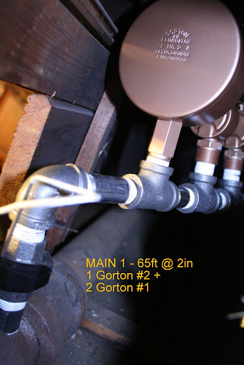
Vent Location "0" .. beginning of Airtube Bypass ...
Vent Location 1 .. end of Airtube Bypass ...
Boiler Lower View ...
Boiler Full View with Vent Location 2 (it IS VENTING) in Background .. There is still a slight banging in the horizontal return in far right corner .... but it quiets pretty quickly . and must be better that having a boiler empty/full every other day with the MAINs BANGING at 5AM.
the terrible U

My fish stick ... after 4hrs of fishing .. the far end is where I need it ..
the "near end" goes to snag again ..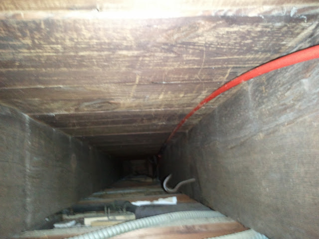 1-pipe Homeowner - Queens, NYC
NEW: SlantFin Intrepid TR-30 + Tankless + Riello 40-F5 @ 0.85gph | OLD: Fitzgibbons 402 boiler + Beckett "SR" Oil Gun @ 1.75gph
installed: 0-20oz/si gauge | vaporstat | hour-meter | gortons on all rads | 1pc G#2 + 1pc G#1 on each of 2 mains
Connected EDR load: 371 sf venting load: 2.95cfm vent capacity: 4.62cfm
my NEW system pics | my OLD system pics0 -
Quite an effort
I sure do hope the air bypass works out well because it looks like it was quite a job to install. Didn't realize how nicely finished the basement was until I saw your photos.
Still thinking about why it works, but there are all sorts of changes of pressure in the return during a steam cycle which were being altered by the several feet of water in the trap. Then there was the syphon effect and flooding which the bypass loop eliminated.
In the end it really just brings the state of the return back to what it was before the renovation. If it worked before it should work the same now as it did then.0 -
Looped since 1934
A while back someone asked where the "Loop" was depicted in the Dan Holohan books? "The Lost Art of Steam Heating" see page #95 and "Linhardt's Field Guide to Steam Heating" see page #166.
Note the Loops are "to get past obstructions" or "looping main around steel beam". This application is >>>>looping around two door frames0 -
Looped since 1934
0 -
today's report ...
so far so good ..
although I didn't visit today, I spoke with my cousin and he reported that the water level was maintained ..
there was some "tinking" in the pipes .. likely the one in the boiler room .. I feel that if I remove the vent from Location #2 .. the steam will not travel down the side-wall pipe and I will eliminate the "tinking" in the boiler room.
I know, I know .. steamhead already told me this. Sometimes I just have to figure it out myself :-)1-pipe Homeowner - Queens, NYC
NEW: SlantFin Intrepid TR-30 + Tankless + Riello 40-F5 @ 0.85gph | OLD: Fitzgibbons 402 boiler + Beckett "SR" Oil Gun @ 1.75gph
installed: 0-20oz/si gauge | vaporstat | hour-meter | gortons on all rads | 1pc G#2 + 1pc G#1 on each of 2 mains
Connected EDR load: 371 sf venting load: 2.95cfm vent capacity: 4.62cfm
my NEW system pics | my OLD system pics0


This discussion has been closed.
Categories
- All Categories
- 87.7K THE MAIN WALL
- 3.3K A-C, Heat Pumps & Refrigeration
- 59 Biomass
- 430 Carbon Monoxide Awareness
- 128 Chimneys & Flues
- 2.2K Domestic Hot Water
- 5.9K Gas Heating
- 121 Geothermal
- 170 Indoor-Air Quality
- 3.8K Oil Heating
- 79 Pipe Deterioration
- 1.1K Plumbing
- 6.6K Radiant Heating
- 396 Solar
- 16K Strictly Steam
- 3.5K Thermostats and Controls
- 56 Water Quality
- 51 Industry Classes
- 51 Job Opportunities
- 17 Recall Announcements