Welcome! Here are the website rules, as well as some tips for using this forum.
Need to contact us? Visit https://heatinghelp.com/contact-us/.
Click here to Find a Contractor in your area.
If our community has helped you, please consider making a contribution to support this website. Thanks!
Boiler piping
Options
Greg Maxwell
Member Posts: 210
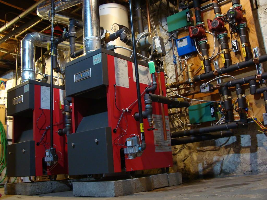
I'm involved in a job where we are going to take 2- 7 section Biasi SG boilers and pipe them together to a common main. The boilers will be 1-1/2, piped into a 2" main. I would like to know if anyone out there has a piping diagram for injection from each boiler into the main, so I dont have to flow through both boilers at the same time. The boilers are going to be staged - lead/lag.
0
Comments
-
P/S
Using primary/secondary you can join them in parallel into the main. I usually set the controls to alternate which boiler leads every X amount of hours.:NYplumber:0 -
taco
Has a nice control package for just this type of setup. Simple but effective...0 -
Boiler piping
We are going to be using an AQ251 H/W control on this, I am just wondering about piping the boilers into the main. I'd like to use injection. Each boiler will have its own pump.0 -
you might try this
The Knight install manual has great diagrams. Page 40 might be what you are looking for.
http://www.lochinvar.com/_linefiles/KBII-I-O%20Rev%20D.pdf
Hope this helps.
Larry0 -
Piping
http://www.comfort-calc.net/Multiple_boiler.html
Check this drawing one. It is very simple but the point is made.0 -
Low Loss Header
Gets piped the same way as multiple condensing boilers.
http://www.caleffi.us/en_US/caleffi/Details/Magazines/pdf/idronics_1_us.pdfThere was an error rendering this rich post.
0 -
2" sounds small
For 2- 7 section boilers. My gut reaction would have been 3" or at least 2 1/2".0 -
Pipe sizing
ME is spot on. Each of those boilers has a heating capacity of 279. Boiler supply and returns need to be 2" and the header 3" to move the 558 if your designing around a 20 degree delta-t.There was an error rendering this rich post.
0 -
Main Size
Looking at a velocity of 5ft per sec for 50gpm, and a head of 4.6ft, my chart says 2".0 -
parallel pipe
them. It can be done with or without a hydro-separator, depending on your pumping requirements on the boiler and load side.
Be sure the piping is sized for the flow rate you are desiging around.
hrBob "hot rod" Rohr
trainer for Caleffi NA
Living the hydronic dream0 -
Parallel
Rod, I like that piping diagram. I'll forward that onto the contractor. I however wont use a hydroseperator, I'll figure closely spaced tees. Seperators are an aweful lot of money for whet they are.
Thanks0 -
Seperators are an aweful lot of money for whet they are.
Since I am not a pro, I do not know the answer to this question. I know what the manufacturers of hydraulic separators say.
If you include the cost of an air extractor and a dirt separator, and the labor of plumbing them in, is the cost of an separator still unreasonably high?0 -
Exactly
And we haven't even talked about no temp drops across the zones.There was an error rendering this rich post.
0 -
no temp drops across the zones
Can you explain that? If you have closely-spaced Ts instead of hydraulic separator, and the common pipe on the load side is sufficiently large (which would be required with hydraulic separator as well), you would not get temperature drops with the Ts either, it seems to me. Drops with Ts would be a problem if you used separate pairs of Ts in series, one for each load (which would make sense sometimes).0 -
Hydraulic seperators
Yes, by hundreds0 -
Not On a 20
Degree delta-t you won't. Need 2-1/2 at 5ft per second. Ran it thru Siggy's software just to check myself.There was an error rendering this rich post.
0 -
No Temp Drops
Because I would be piping antler style as shown in HR's pic above on the secondary side. You might be interested in these JD
http://www.caleffi.us/caleffi/en_US/Site/Technical_library/Idraulica_magazine/index.sdoThere was an error rendering this rich post.
0 -
Buffer
Buffer tanks offer a lot in one package. I have been incorporating them into all my installations and have been more than pleased with the outcome. Results are as follows: air separation, dirt separation, hydraulic separation, parking space for btus, and if there is an internal coil, hot water or snow melt can be used too. :NYplumber:0
 -
2" Pipe.
The last time I looked, 2" pipe would only carry about 450 MBTU at a 20* delta T. You need to up size to 2 1/2" to carry that load. You calculations didn't take into account the delta T.0 -
I have looked at Caleffi's hydraulic separators...
... and they seem to be fine devices. If you do not get labor for free, it seems to me that it makes a lot of sense to use one of these instead of closely spaced Ts, an air extractor, and a dirt separator.
However, the losses to which you allude would be the same whether you used closely spaced Ts near the boiler supply and return, or whether you used an hydraulic separator. On the load side, if plumbed as in the illustration, above, the parallel piping would be the same whether one used an hydraulic separator or the closely spaced Ts. The thing called "field constructed headers (typical)" would determine the temperature loss between the various load circuits, and provided those are of sufficient diameter, the loss should be negligeable.0 -
Pri/Sec
Your correct in that blending inside the LLH produces as drop in water temp but I am referring to a drop across the zones as multiple zones open. In a true primary secondary piping arrangement you do. I'm using my i-pad so don't have a diagram to show you but did find this nice articlen written by our host.
http://t4engr.com/understanding_primarysecondary.htmThere was an error rendering this rich post.
0 -
Wrong thread
Hey ME that was his other thread on the piping. I think you mean 35gpm on a 20.There was an error rendering this rich post.
0 -
I am referring to a drop across the zones as multiple zones open.
I do not know what you mean by a "true" primary-secondary piping arrangement. There are several primary-secondary arrangements I have seen. One is shown in the diagram that appears earlier in this thread. I would consider that "true". Another would have a series loop on the load side of the closely spaced Ts, with a set of closely spaced Ts for each load drop; there would be a circulator to drive flow through this secondary loop. I would consider this as "true" as the first. In this arrangement, the first load loop, would get the hottest water, and each following loop would get colder water (assuming all loops were running). But this would be the same whether the primary loop (the one containing the boiler(s)) were separated from the secondary loop by closely spaced Ts or an hydraulic separator.0
This discussion has been closed.
Categories
- All Categories
- 87.3K THE MAIN WALL
- 3.2K A-C, Heat Pumps & Refrigeration
- 61 Biomass
- 429 Carbon Monoxide Awareness
- 120 Chimneys & Flues
- 2.1K Domestic Hot Water
- 5.8K Gas Heating
- 115 Geothermal
- 166 Indoor-Air Quality
- 3.7K Oil Heating
- 77 Pipe Deterioration
- 1K Plumbing
- 6.5K Radiant Heating
- 395 Solar
- 15.7K Strictly Steam
- 3.4K Thermostats and Controls
- 56 Water Quality
- 51 Industry Classes
- 50 Job Opportunities
- 18 Recall Announcements


