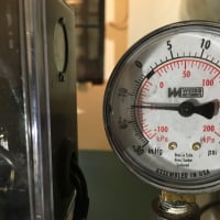
Inlet orifices & pics of valves.

This building was built in the early 50s, in central Ohio. After reading a few of Dan's books, I believe the design pressure was most likely 2 lbs. I expect the system will work correctly at 2# (as well as it is able to in it's current state of repair) . That said, I'd like to see if it will run at a lower pressure. However, to go to, say 1#, would require a different set of orifices than 2#, correct? Also, the building is 2 stories, about a hundred & forty feet long (boiler nominally central, 1st floor). What are the odds that less than 2# will suffice to move steam to the furthest radiators? Should I just leave the pressure at design?
Comments
-
It has been said on this site and in Dan't book many times the Empire State Building heats with 3PSI steam pressure. I don't think you are anywhere close to that size so lower pressure should be fine. I noticed you used Honeywell TRV's, did you add vacuum breakers to them? Just checking because I have seen many people on here that don't realize that needs added to the Honeywell TRV's. The Danfoss actually have this feature built in already, that is most likely the reason for the price differential.0
-
I have 3 storeys, with 55 radiators, and most of my heating is at 2 ounces. The fact that you have some sort of pneumatically controlled system may require a higher than needed pressure. I would try as low a pressure as possible, and move up from there.--NBC0
-
Your hand knob valves look a lot like the ones I contended with (1954 job); Hoffman 180 or 185. From the book it shows the 185 to be a modulating valve with a pointer attached to the knob. I think the difference was that there were more turns from open to closed in the 185 than in the non-modulating 180.
In any event Hoffman has no replacement parts for either valve. (The parts book I have is dated 2001-2002.) They offer a replacement of a 185C which if I recall has a different pattern from inlet to center line of outlet. I had eleven 1/1/4" valves in need of repair, a bear to get to and little flexibility to move pipes. So I was able to unscrew the bonnet and remove the guts. Cleaning up the moving parts and lube with hi temp grease they then would function (rotate). However the composite disc on all was pretty shot, the valve is still used to modulate on a rough basis. The orifice does most of the work of regulation. There were smaller valves which were replaced with lesser quality RWV brand, but they do what the high dollar Hoffman replacement would do. Also some parts of the smaller sizes fit in the 1 1/4" sizes.
I sized the orifices for 2 PSI, the pressuretrol takes the boiler up to 2.25. The boiler short cycles every 6 to 8 minutes. The pressure could be lowered but the cycles would get shorter.
We have a 1,080,000 BTUH input boiler using 602, 011 BTUH (that includes 1.33 pickup).
this building has more than 350' of steam main on the 2 pipe system. It starts out with 4" pipe and eventually reduces down to 2". It was originally a coal burner, now has NG burner installed in the 1955 boiler. I don't know what pressure was used for the piping design. Pipes seem big enough for vapor pressure. But being this oversized, I'm not sure what to do with this.
The Henry Gifford chart shows that for 63 EDR at 2 PSI your orifice would be 7/32".
An extended chart for 63 EDR at 1 PSI indicates an orifice of 5/16"......so if you could drop the pressure and still needed the 63 EDR. You would drill a larger hole.
If the pressure was dropped to 1 PSI and the 7/32" remained then you would only have 30 to 33 EDR at that rad. (Sometimes enough for the situation).
This seems to be a chicken and egg conundrum; you dance with lowering pressure and increasing orifices. But in most cases there is too much heat already delivered to rooms, especially if upgrades have been made.
Popping out and redrilling orifices would not take very long if all your radiation is open CI. ( Most of mine are in convectors buried inside/behind bookcases.)
Is your pneumatic system of the day/night design?
New traps will certainly keep steam out of the dry returns and allow you to overheat rooms more efficiency than previously.
I hope others more experienced with this will comment.
 1
1 -
Thanks, all of you! To go in order, the trv pictured predates me - it's the only one that was installed when I took over. It doesn't work, either. That said, I am using the Honeywell V110 valve with T104 thermostatic control heads. No vacuum breakers, the instructions didn't mention them. Are they critical? Where/how would they mount? They seemed to control properly, but I've only replaced four so far. I would like to use them everywhere I can, but they're coming out-of-pocket so it'll be slow going.
I'm concerned about the pressure for several reasons. I'd like to use the lowest I can get away with for efficiency's sake, but comfort is a concern as well. I believe it'll Just Work at 2#. I suspect that it'll Just Work at less than that as well, but without consulting with the original engineer that's just a guess that'll have to be born out with experience, but there's a lot of work that will be wasted if I guess wrong.
The hand valves are everywhere but the classrooms (those are pneumatic wall stats), & seem to be where the trvs will be the biggest win - stairwells, cafeteria (already a few trvs) restrooms, etc. I see now that the next step is going to have to be a real survey, both as to EDR as well as controls & traps.
Attached are a few pics of the boiler. Note the appendix on the header, I intend to remove that once I've bulked up enough to swing the pipe wench. ^_^ Also note the two valves with the series 90 actuators attached - they are part of a non-operational setback system. They don't appear to be closed, as the whole place heats fine (as best I can tell). The risers are 4", the drop header is 6". It's not quite kosher, but it seems to dry the steam out just fine. The only noise the creaking of pipes when the system goes from cold -> hot. No hammer any time ever.
I included a pic of the first underground leak I had repaired. Only one to go! I hope!0 -
Are all your rads of 2 pipe design?
I believe that TRV for one pipe systems need a vac bkr on the rad because they handle venting air in and out of the rad.
I believe that TRV's for 2 pipe systems might not need a vac bkr because they are operating the inlet valve just as you would if you adjusted the heat manually with the valve.
Do you have any place where the steam pressure must lift condensate up to get it into a return pipe? From reading Dan's books I believe that would be one of the times where 2# or less might not work. Your first picture of a hand valve looked like it might be a downfeed steam main that was dripped.
Do your pneumatic wall stats have a lever that might indicate day/night or occupied/unoccupied?
If I could ask what this building would be used for in the future?
You said it was previously a school. 1
1 -
My apologies about mentioning the vacuum breaker. Yes on 2 pipe that shouldn't matter. Didn't mean to confuse the situation. I just looked up that boiler (Peerless series 211A?) and there appears to be at least one item in the piping that isn't to manufacturers spec. Peerless specifically states threaded elbows to create swing joints with the header. I attached the I&O manual in case you don't have it.0
-
What's the circulator for?0
-
The steam system is two pipe. I don't lift condensate anywhere, although that was considered before I decided to repair the underground leak.
I haven't looked at the IOM for the boiler yet, mostly because it's working, and I'm prioritizing my hair-pulling.
The circ is for the second addition, which is a water loop. (first addition is steam fan coils w/ pneu. stats.) The heat exchanger was replaced a few years ago, & aside from a thaw-out when the boiler locked out, stats leaking air & out of cal, & a bad fan motor in one unit, that system is working fine. ^_^
0 -
I know some one will say it sooner then later .Want to save some money insulae your piping with a good 1 inch wall fiberglass pipe insulation your fuel bill will like you and your system will perform better .Also if your using a steam to water heat dont get glued to low pressure in some cases lower steam pressure may equate to lower btu output from your heat exchanger just something to consider .Insulating your system piping will less any water hammering and produce less condensate in the mains and waste less fuel .Every systemi that i have worked on that had no insulation suffered many issues included hi fuel cost ,uneven heat,water hammer and some rotted mains from so much condensate flow usually at the fittings .Just wondering if you have any crossover traps and is this system gravity or pumped returns .peace and good luck clammy Insulate those dam pipesR.A. Calmbacher L.L.C. HVAC
NJ Master HVAC Lic.
Mahwah, NJ
Specializing in steam and hydronic heating0 -
Speaking of orifices,inlet orifices (or valves) hopefully limit the steam going into radiator.If insulation and windows have been improved then rad is oversized and all that limited steam will condense,and thermostatic traps are unnecessary.At least I think so.I also think that outlet orifices are a good idea to make the pressure in radiator (again hopefully) higher than in return pipe downstream of outlet orifice. On the other hand I've seen buildings without orifices or traps on radiators work pretty well.0
-
Jumper, it seems to me that the phase change from vapor to liquid would create pressure drop in the rad. Also there were numerous inlet valve orifice systems in the "Lost Art" that are still around and working.
Or think of an oversized and underpiped 2 pipe rad. would it never get hot all the way across? And if so then the trap would never close??
Orifices are fairly pricey for what they consist of. But the demand must not be that high and would be a reason for the cost. But a fraction of the cost of a trap element and something that never wears out in your lifetime. However for every orifice installed there is possibly one less new trap element sold (every 5-10 years).
I'm waiting for the other shoe to drop as to why they are not a good idea. I have limited hands/wrenches on experience on this subject but so far things have been favorable.0 -
I think the Mepco valve which is able to meter the steam would be easier to manage than orifice plates; however with a higher cost. Reduce the firing of an oversized burner, and you should finally have a balanced system.
I don't think an orifice on the return will be nearly as effective.
One thing to consider when using supply side orifices, is the slower rate at which the air is pushed out from a cold start, unless........you are running sub atmospheric!!!--NBC0 -
I agree that phase change drops pressure.But something has to push air to maintain circulation.
You can make your own diaphragms.What resists erosion? It's sizing that can be tricky.Trap salesmen will tell you that traps save energy.0 -
The system I worked on would have originally vented all air thru the traps into the return, which would vent air thru some since long gone (removed by others) eliminator which used the chimney for draft assist. So the steam mains now have 2 sets of Gorton #2 each. The mains which were dripped into the wet return at the boiler are now vented like a single pipe system.
Each rad vents thru its orifice and then thru an empty trap into the dry return which also has Gorton #2s installed.
Sizing was based on more pressure than what the system does actually run at. The theory being that if more heat is needed in an area the orifice could be drilled larger. This house has had an upgrade in insulation since 1918.0 -
Yah, insulation is on my to-do list. I need to hold off for now though, as there is still piping to rework. Purely for an efficiency gain however, as I don't have any water hammer issues. This system is pumped return (original design, not a misapplied retrofit), numerous drips that are trapped, & must remain so AFAIK, so no orifice for them. There's a big bucket trap on the end of the header, and another large one on the steam->water heat exchanger that's active when we're starting up, so the air leaves pretty quickly.
The inlet orifice will restrict the amount of steam & therefor the btus going into the radiator to no more than the radiator can condense at a specific indoor temp. Google "BSEOrifices.pdf" for my source. Seems convincing, but I'm just a washed-up electrician. ^_^
I too am wondering what the down side to orifice inlet plates is. So far, the worst thing I've read about is that it'll delay recovery somewhat as we can no longer crank out the btus like before. I would think, however, that that might be somewhat offset by our lower temperature, which might influence the pressure across the plate & therefore the capacity of the orifice. I dunno.
Return orifices seem to be nothing but trouble, I can't see why anyone would use them in this application. As the hole is a fixed size, it'll either be too small for initial startup if it's sized for steady state & hold the radiator full of water, or too large for steady state if it's sized for startup & a trap or something will still be needed to keep steam out of the returns. There is a comparatively lot of information available on outlet orifices!
My system sounds similar to your system @JUGHNE, save that I still have my original vent. Everything vents back to the condensate receiver & from there out a 3/4" pipe. This was a parochial school, a charter school now leases the building. (As they pay their bills, I really want to keep them happy!) The insulation is arguably worse now than when the bldg was new, the holes cut in the windows to fit the window rattlers weren't there when it was built!
What are your orifices sized for, what pressure do you run at, what is the design pressure? It's a concern of mine that I'd be locked into a system pressure by the orifice size. There might be fifty or more radiators where an orifice would be ideal; I'd hate to have to change them all out several times. I think that 1# is doable without significant changes to the orifices, but that's a WAG on my part.
0 -
Downside to inlet orifice plates is that time adds up if you have to change them. XXIst century trend is automatic valves.
As for return gizmos,doohickies with no moving parts have a particular charm.0 -
The main problem with orifices, as I see it, is the slower removal of air. This could be easily solved by going sub-atmospheric, with no air to remove.--NBC0
-
NBC, are you concerned with air removal from the steam main, or the air removal for the individual rad. Or both?
Some means of venting the steam main other than thru the rad orifices needs to be put in place, IMO. This is a cond pumped return system as Ratio stated above.
Ratio, do you know how close your connected EDR matches the boiler output? There is a possibility that the blueprints exist somewhere; there may be all the piping and EDR connected load.
My 1954 school prints were located and proved very helpful.
My 1961 parochial school has a "Print/plans Vault" built into the wall, (just like a wall safe would be). It is about 8' off the floor and all you see is about a 5" cap with a lock. If you snoop around the admin area/store room you could get lucky") 1
1 -
I was thinking of all the air in the system.
With traps, there is more steam flow at the beginning to push the air out quickly; whereas with the orifices, the flow is reduced, taking a bit longer to get the air out. This is where the advantage of sub-atmospheric operation shows up-much less air to remove with each heating cycle. This probably make an oversized boiler, with its short-cycling more even to heat throughout.--NBC0 -
Aha, the first real downside. Hmmmm.... might not even be an issue for me, even going with a 1/8" orifice everywhere I've got so many that the 3/4" main vent is probably going to be the limiting factor.
WRT EDR, a hot boiler will cut out at 2# in a matter of minutes, even starting from 0. Significantly over-sized is my guess. It's possible that the old control valves that were used for the setback system aren't completely opened, but the system seems to get steam out to the radiators fast enough. I don't know how this boiler was sized - it's a replacement from a year or so before I came on board. Maybe these old pneumatic control systems used over-sized boilers.
The apparent sizing issue is why I dearly want to modulate the burner. With even just 4:1 turndown, I should be able to keep the burner lit for most of the season, perking just enough to meet the load.
If I can get all the real problems cleared up, I might look into rehabbing the setback system too.
0 -
Ratio you seem to have fallen off of the radar. IMO you have to know your connected EDR to get an idea of the situation. ( You could be bringing a knife to a gunfight)
") If you want to do the inlet valve approach you would have to know the EDR of each rad.
If you want to do the inlet valve approach you would have to know the EDR of each rad.
And I was born in the first half of the last century so enlighten me as to what WRT means. (I don't think it is water return temp).
Is the 3/4" main vent you refer to the vent pipe on the condensate pump?
The 4 to 1 turn down on a boiler that size sounds great but is it realistic to do? The I & O manual only mentioned changing NG orifices. Someone above mentioned a change in gas valve train approved by Peerless.0 -
Still here, but the excrement hit the air movement device at work, of course it's the job an hour & a half away. Another 500 mile week. Also, I'm going to have to order another of Dan's books. My collection is nearing completion!
WRT -> With Regards To. I've picked up some bad habits emailing on my phone.
The main vent is indeed the vent on the condensate tank. I know I've got traps leaking through, I've seen a steam plume coming out, but either due to the distance to the vent or the minorness of the leaks, it doesn't seem to be excessive. (I suspect the former, not the latter!)
The 4:1 turndown is just what Maxitrol claims for an atmospheric burner configuration of their MR251D valve. I've also seen ball valves with actuators on the handle, & the old butterfly throttle valve assemblies that the old guys used.
As near as I can figure, the limit to turndown is stable burning at low input rates. It almost seems to me that a better way would be to close off each orifice individually, one at a time. I think then that we'd maintain a more stable burn, as the primary air would be the same at each particular burner no matter what we modulate to/stage in. Secondary air would be somewhat affected too I think, but I dunno how big the influence would be. In any case, it isn't something that I'm going to actually do until most/all of my real problems are taken care of. But I like thinking about it!
0 -
I think your idea has been used in the past. In effect two atmospheric burners for discrete control. Hopefully low stays on all season.ratio said:As near as I can figure, the limit to turndown is stable burning at low input rates. It almost seems to me that a better way would be to close off each orifice individually, one at a time.
0


Categories
- All Categories
- 85.6K THE MAIN WALL
- 3K A-C, Heat Pumps & Refrigeration
- 51 Biomass
- 423 Carbon Monoxide Awareness
- 71 Chimneys & Flues
- 1.9K Domestic Hot Water
- 5.2K Gas Heating
- 92 Geothermal
- 149 Indoor-Air Quality
- 3.2K Oil Heating
- 60 Pipe Deterioration
- 850 Plumbing
- 5.8K Radiant Heating
- 375 Solar
- 14.5K Strictly Steam
- 3.2K Thermostats and Controls
- 51 Water Quality
- 38 Industry Classes
- 55 Job Opportunities
- 18 Recall Announcements